foundingpower programmable bms

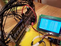
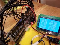
Recently I've received some questions about OLED display - cable extension.

Original cable is quite short and if you would like to have display on a longer cable, you must take some precautions to have a proper functionality and avoid interferences:
- You must make new cable (I don't reccomend connectors to make cable extender).
- Cable must be shielded, shield must be connected to battery minus! There's plenty of EMC in e-vehicle, which cause interferences on data lines!
- Cable wires must not be too thin. I also don't reccomend "hard wire", but "soft one".
- Put 10 or 22 uF (best fit SMD 0805 size) ceramic capacitor between pins 1 and 2 of OLED! (on OLED side).
- Put 100 nF capacitor on the button pins.

With this, cable can be longer, length up to 5 m is tested in several electric cars. If andy interferences happen, this is usually due to improper cable grounding (shield). However, shorter cable is always better, so try to avoid longer lengths if possible!

Regards,
Gregor
 
how to connect CS-BMS to the Kelly controller for Recuperation?
You can speed the display?
 
Both current directions are supported, so there is no special settins required for recuperation current.
I don't understand second question. If you think, if speed can be shown on a display, answer is no, just battery data.

Regards,
gregor
 
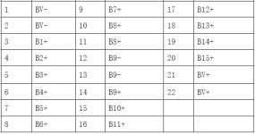
Anyone have the 16S model of this BMS? I got mine today, looks great, but I noticed something... 16S should have 17 wires. This has 18.

Two of the thick wires are labeled "B8+" and B9-". Am I mistaken or do these connect to the same spot on the battery?

I got this connection diagram in my email (attached), and it says pins 10, 11, 12, and 13 are all B8+ and B9-. What's the sense in having 4 wires going to the same connection, when all the other cells get only 1 wire?
 

Attachments

  • unnamed.jpg
    unnamed.jpg
    22.1 KB · Views: 4,046
Yea it's just the way that BMS works. It is a bit confusing. Obviously the + and - where the 4 wires go are the same spot , but
when I sat mine up I probably spent a hour over thinking it and in the end wish they would have just called them the same.

I think I remember the reason being how the bms is powered or something. I am sure mucek will chime in he's provided as good
as support I could ask. I am running the latest BMS he sells as 24s with the bluetooth & display now. It is really nice.

The only downside I have is the metrics are all geared towards UK (ok I know the USA is different then everyone else what's new).

If you read thru this thread some others have made diagrams of their wire setup.
 
Hey thanks for the response!

I think I can figure it out. The rest of it should be pretty straightforward. On my model it's just the 18 cell wires, four temperature probes, and the B- and P- (battery negative, load negative) main power cords. The others, the switch and the LCD are self-explanatory.

Mucek looks like he has great service, but I didn't buy from him, (unfortunately his prices are nearly 3x higher than what I'm willing to pay, and he doesn't offer a 16S version), so I don't expect any help from him.
 
@Inedible: You are right: this is the same spot and it's done this way because of LTC chips logic. It's no sense having 4 wires actually, you can only use one :).

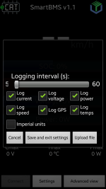
@Ohzee - YOU'LL LIKE THIS! :)
A new Android app version with imperial units is out! :p :p :p
(download from webpage, just install APK and it will upgrade the old version)

Regards,
Gregor
 

Attachments

  • smartbms.png
    smartbms.png
    44.2 KB · Views: 3,984
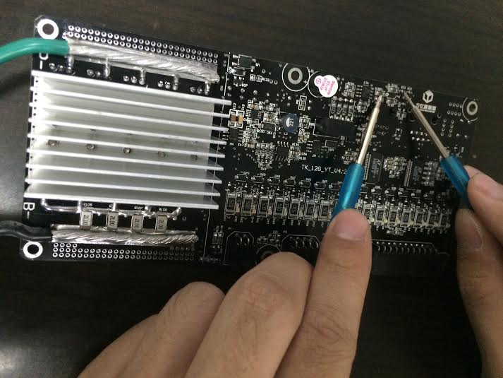
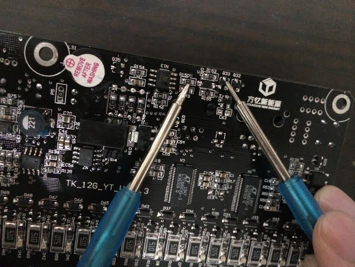
Ok, any chance anyone knows what resistor R150 and transistor Q33 do on the 16S version of this BMS?

dFRohDG.jpg


I had a problem where the BMS said my bike has a short-circuit, even though the bike seems to work when I bypass the BMS.

Eason contacted me via AliExpress's messaging service, told me to remove these two components.

I removed them and everything seems to work perfectly now. This is great news except I don't know what I just did.

7iOhEiK.jpg


Did I just disable the short-circuit protection on the BMS? My bike doesn't seem to have a short. I think I ought to know if it did. I figure there would be fire involved. Yet, when I plug a multimeter into the battery connections and set it to resistance, it starts off at 0.000 ohms, then slowly rises in resistance up to 3.5 megaohms or so when it levels out. Not sure why that is. Capacitors maybe?

I've run into the language barrier a lot when talking to Eason. He seems like a great guy, very eager to help, but I've asked him a couple times now, what's the deal with Q33 and R150 and he still hasn't responded to that. He seems to ignore questions that he has a hard time answering.
 
Hi!

I am not familiar with this BMS circuit, though there might be seen, where it is connected and based on this suspect its function. Can you please send me high res images of PCB (both sides, some different angles) on my email (info at ecat dot si) - do mind, that you take photograph from some angle, so marks on chips are readable?

Regards,
Gregor

p.s. Due to my experiences, this "short-circuit" protection with MOSFETs doesn't work pretty well (if you make a REAL shortcut, MOSFETs will burn and go into "short-circuit" state). So I REALLY suggest you using a proper fuse to protect the battery from short circuit. (place fuse as close to the battery as possible - usually directly on pin).
 
WOW mucek not sure how I missed your post until now , but THANKS.

My riding season is currently on hold as it's getting into winter, night time comes so much earlier I just have not gotten out any.
Still come spring that will be an update I will very much appreciate.

There any chance of doing the same for the BMS itself ? Since I have the display now it's going to be the primary way I interface
with the unit as it's that much easier.

Still love the product. Going to put together an 18650 battery soon and plan on using this baby over there.
 
Thanks Mucek, but Eason already contacted me and confirmed that removing Q33 and R150 does disable the short circuit protection. That's ok, I do have a circuit breaker anyway.
 
Finally home! :)
Happy new year to all smartBMS users!

Regards,
Gregor
 
hello dear Smart BMS users,

i have the Smart BMS LTC6803-3, it's new in box and just now i connected it to my PC.
USB driver is set o.k.
http://my.jetscreenshot.com/4755/20150112-cgkw-28kb.jpg

The BMS recognized the 10s li-ion battery pack, but not connecting to PC.

It found port-6 on PC, but when i press "open port" it gives the error "open port failed !! "
http://my.jetscreenshot.com/4755/20150112-wdgl-133kb.jpg

i think my software is old version - 3.0 version.
does anyone here can send me the new software?
i searched the updated software for long hours, and did not find it on the Web,
(jason, the guy i ordered the BMS from, is not answering to my mails).

mucek, i read a few post with some beautiful answers you gave to people, thanks for your service.

any help will do to set this BMS to work right

thanks
ilan
 

Attachments

  • Smart_BMS_LTC6803-3_3.jpg
    Smart_BMS_LTC6803-3_3.jpg
    179.1 KB · Views: 3,685
  • Smart_BMS_LTC6803-3_5.jpg
    Smart_BMS_LTC6803-3_5.jpg
    157.1 KB · Views: 1,930
  • Port_Open_Failed.jpg
    Port_Open_Failed.jpg
    106.7 KB · Views: 1,647
dear wpym,
can you please send the new software BMS_V4.3_EN.rar to my mail:ilan.neworld@gmail.com or skype: ilan.neworld ?
(if you can uploaded it here, it will be great for me and for other people who's lost with this issue)

i think my software is old version - 3.0 version, so i have this error "port open failed !!"

I searched for long hours on the web for the new software, and did not find.
(jason, the guy i ordered the BMS from, is not answering to my mails).

any help will do.

big thanks
ilan
 

Attachments

  • Port_Open_Failed.jpg
    Port_Open_Failed.jpg
    106.7 KB · Views: 1,647
  • Smart_BMS_LTC6803-3_3.jpg
    Smart_BMS_LTC6803-3_3.jpg
    179.1 KB · Views: 3,684
As you already found out, you need proper software version for this BMS. Unfortunnatly I don't have one, but I may ask Eason to provide it and then I can upload it here.

Regards,
Gregor
 
update for jason mail:

"
Delivery to the following recipient has been delayed:

sales@foundingpower.com
"
 
Eason sometimes takes a few days to reply, and he has a bad problem trying to send email attachments.

Here's the software: https://mega.co.nz/#!lEgWFQAL!-G-SWfO2rG1alL-UdBf9-trc5cyTCgvwAuZEdZ3H0iE
 
thank you inedible, this is great service you did for me!!

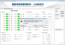
i installed the software (after removing the old one) and after i press "open port", it give this error:
"Unhandled exception has occurred in your application..." and it does not look like opening the port or connecting to BMS.

i attached the screenshot, and this is the full error message.
any help will do:

See the end of this message for details on invoking
just-in-time (JIT) debugging instead of this dialog box.

************** Exception Text **************
System.ApplicationException: 写Ini文件出错
at ProtectModule.MainForm.button29_Click(Object sender, EventArgs e)
at System.Windows.Forms.Control.OnClick(EventArgs e)
at System.Windows.Forms.Button.OnMouseUp(MouseEventArgs mevent)
at System.Windows.Forms.Control.WmMouseUp(Message& m, MouseButtons button, Int32 clicks)
at System.Windows.Forms.Control.WndProc(Message& m)
at System.Windows.Forms.ButtonBase.WndProc(Message& m)
at System.Windows.Forms.Button.WndProc(Message& m)
at System.Windows.Forms.Control.ControlNativeWindow.WndProc(Message& m)
at System.Windows.Forms.NativeWindow.Callback(IntPtr hWnd, Int32 msg, IntPtr wparam, IntPtr lparam)


************** Loaded Assemblies **************
mscorlib
Assembly Version: 2.0.0.0
Win32 Version: 2.0.50727.5485 (Win7SP1GDR.050727-5400)
CodeBase: file:///C:/Windows/Microsoft.NET/Framework64/v2.0.50727/mscorlib.dll
----------------------------------------
ProtectModule
Assembly Version: 1.0.0.0
Win32 Version: 1.0.0.0
CodeBase: file:///C:/Program%20Files%20(x86)/FoundingPower/BMSSetup/ProtectModule.exe
----------------------------------------
System.Windows.Forms
Assembly Version: 2.0.0.0
Win32 Version: 2.0.50727.5483 (Win7SP1GDR.050727-5400)
CodeBase: file:///C:/Windows/assembly/GAC_MSIL/System.Windows.Forms/2.0.0.0__b77a5c561934e089/System.Windows.Forms.dll
----------------------------------------
System
Assembly Version: 2.0.0.0
Win32 Version: 2.0.50727.5485 (Win7SP1GDR.050727-5400)
CodeBase: file:///C:/Windows/assembly/GAC_MSIL/System/2.0.0.0__b77a5c561934e089/System.dll
----------------------------------------
System.Drawing
Assembly Version: 2.0.0.0
Win32 Version: 2.0.50727.5483 (Win7SP1GDR.050727-5400)
CodeBase: file:///C:/Windows/assembly/GAC_MSIL/System.Drawing/2.0.0.0__b03f5f7f11d50a3a/System.Drawing.dll
----------------------------------------
ProgressODoom
Assembly Version: 1.0.3806.19710
Win32 Version: 1.0.0.0
CodeBase: file:///C:/Program%20Files%20(x86)/FoundingPower/BMSSetup/ProgressODoom.DLL
----------------------------------------
ColorButton
Assembly Version: 1.0.3806.24765
Win32 Version: 1.0.3806.24765
CodeBase: file:///C:/Program%20Files%20(x86)/FoundingPower/BMSSetup/ColorButton.DLL
----------------------------------------
RedFlag
Assembly Version: 1.0.0.0
Win32 Version: 1.0.0.0
CodeBase: file:///C:/Program%20Files%20(x86)/FoundingPower/BMSSetup/RedFlag.DLL
----------------------------------------

************** JIT Debugging **************
To enable just-in-time (JIT) debugging, the .config file for this
application or computer (machine.config) must have the
jitDebugging value set in the system.windows.forms section.
The application must also be compiled with debugging
enabled.

For example:

<configuration>
<system.windows.forms jitDebugging="true" />
</configuration>

When JIT debugging is enabled, any unhandled exception
will be sent to the JIT debugger registered on the computer
rather than be handled by this dialog box.
 

Attachments

  • Smart_BMS_error_message1.jpg
    Smart_BMS_error_message1.jpg
    115.7 KB · Views: 1,648
According to google translate, that chinese text says "Ini file write error" meaning it's having a problem writing its configuration file.

Maybe try running as administrator? Maybe also check that the configuration file exists and that it's not set as read-only or something. It should be located at: C:\program files (x86)\foundingpower\bmssetup and it's called setup.ini.
 
Hi!

Try to run it as admin, obviously it can't write some system files.

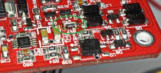
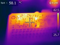
I also found one (old) bug in the new smartBMS circuit (which I thought that was fixed with new PCB revision). When using high voltages (i.e. 24 S LiFePO4 config), it is very likely that after some time (especially if you are using OLED, as it consumes quite high amount of power) resistor R47 (100 ohm, 0805; on resistor is written 101) will get burned. Typical sympthoms are "dead" BMS and sometimes a high frequency sound also can be heard.

The problem is mainly in undersized resistor, as with higher voltages there's quite amount of heat, that this resistor must handle. I suggest you to use 1206 size resistor and instead of 100 ohm use 68 ohm. Mount the resistor 90 degrees to PCB, so it's only touching PCB on one side, but main sides are in air (and can be cooled). The other suggestion is to use standard resistor (THT instead of SMD), which can handle higher powers and can also be touched to the metal casing, which serves as a heat dispenser.

I am attaching some pictures, also thermal one ;)

Regards,
Gregor
 

Attachments

  • smartbms fix.jpg
    smartbms fix.jpg
    173.7 KB · Views: 3,591
  • IR_2131.jpg
    IR_2131.jpg
    171.1 KB · Views: 3,591
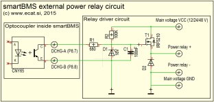
I have received some questions how to drive external power relay switch (contactor) with smartBMS. smartBMS does not have power outputs to directly drive such relay, but has DCHG and CHG optocoupler outputs, which may be used to control the main system contactor. I drawn simple schematics, how to make such circuit using PFET transistor, which is controlled by optocoupler in BMS.

Some remarks:
- PFET (T1) must meet voltage used to drive a power relay (as it's galvanically seperated from the BMS voltage, you may use any system voltage; i.e. 12 V, if vehicle has seperated 12 V power as well) as well as current, which power relay requires (usually few hundreds of mA, but spikes are higher, so take at least few A PFET). PFET on circuit (IRF5210) is way too powerful for such job ... (but won't hurt have more powerful MOSFET then required :) )
- Zener diode (D1) used must have lower voltage then defined gate-to-source voltage in PFET's datasheet
- Don't forget to add D2 diode (any) to block negative voltage spikes

I will draw a (single sided) PCB in the next days and publish it, so you can make it on your own.

Regards,
Gregor

p.s. Same circuit can be used with CHG-A/B pins to control charging. If using enough powerful MOSFETs, you may charge with higher current than smartBMS's internal MOSFETs can handle (30 A). But keep in mind wiring - charging current must go through the main hall sensor, otherwise it won't be measured!
 

Attachments

  • smartBMS ext drive.jpg
    smartBMS ext drive.jpg
    130.8 KB · Views: 1,647
you are just great guys!!
i run the software as admin, and the port is opened.

now please, i have another issue.
1. i connected 13s li-ion battery, and it looks like the BMS is seeing the cells voltage, and giving discharge current.
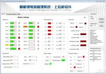
but but is not charged, or showing any charge when i connected the charger. here is some screenshots: 2015-01-20_01-30_System Monitor Version.jpg. 2015-01-20_01-38_System Monitor Version.jpg / not sure if the setting is right.

2. maybe i am dreaming, but it look like there is only 16 channels (16s) to this BMS, how can it work with 24 cells? or, this is a 16s BMS??Smart_BMS_LTC6803-3_5.jpg

3. is someone have the user manual for the 4.3v software? need to know how to set the values and how to work with this software.


thanks for your professional help
ilan
 
So, yes, that looks like the 16S version. There is no way to address more cells, there are only 16 channels on this version. Your best bet might be to run 24 batteries in 12S2P configuration.

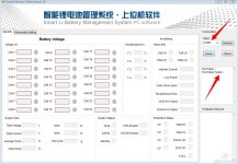
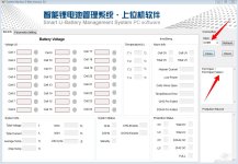
Anyway, I'm not sure what your charging problem is, but you probably need to clear all the alarms first. On the first page of the software, on the right hand side, where it says "alarm info" then "protection status", all of the red boxes are a problem. Anything in the "protection status" should prevent you from charging or discharging.

For instance, in your first screenshot, the errors "UT" and "Total OV" are lit up, meaning you have a "Under Temperature" error and a "Total pack Over Voltage" error.

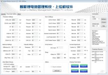
The temperature error is because you do not have your thermal probes plugged in. The overvolt error is because on page two, you have "Total OV" set to 43V, and your pack is currently higher than that. I think you might have meant to set it to 53V instead.
 
1. About the charging I guess, that it's a problem with temperature sensors: from first screenshot I see, that there's Under temperature alarm active (UT) - change NTC num to 0 to disable temp sensors. You also doesn't have set Alarm settings properly.

2. You don't have 24S BMS version - you have 16S version!

3. Sorry, I don't have it, but it's pretty intuitive for me.

Regards,
Gregor
 
Back
Top