Bafang M500/M600 thread

CiDi said:
If you use innomaker you must enter 85116011

Done, but I don't Receive any frame with ID 0x2DD000.
Do I have to look for a different ID because of Innomaker?

PadreParada
 
PadreParada said:
CiDi said:
If you use innomaker you must enter 85116011

Done, but I don't Receive any frame with ID 0x2DD000.
Do I have to look for a different ID because of Innomaker?

PadreParada

Do you have firmware 46.2?
 
CiDi said:
PadreParada said:
CiDi said:
PadreParada said:
Done, but I don't Receive any frame with ID 0x2DD000.
Do I have to look for a different ID because of Innomaker?

PadreParada

Do you have firmware 46.2?

No

Currently the only firmware that works is 46.2
Ok. Have you tried all other firmwares in the GitHub repository?
Anybody knows why bafang doesn´t release 46.2?
 
@casainho, you're an inspiration. I've been following the thread since the beginning and finally I'm starting the build to upgrade my M600 eMTB to your firmware.

I'm interested to hear more about the difficulties you encountered with the magnetic encoder. I'm primarily interested in improving the start-up and low speed characteristics of the motor assistance (it's almost binary with stock firmware which feels downright dangerous during technical maneuvering). Do you think that getting the encoder closer to the magnets (perhaps with a smaller encoder - some are fingernail size) could work? And based on your experience with and without, is the potential benefit at all worth the trouble?

Another improvement I'm hoping to make is readability of the display. The original Bafang display has been difficult to read at a glance in sunlight wearing glasses or goggles, so I'm trying out an ePaper display. Even with all the bit banging in the pure python driver I'm writing, I still get partial updates on a period of 0.75s, which is enough for this purpose I think. Haven't figured out how to get it integrated with Circuitpython's displayio framework, though...
 
Any thoughts on running the motor without the canbus display like shorting the P+ and PL on the UART version of the motor?
 
Any thoughts on running the motor without the canbus display like shorting the P+ and PL on the UART version of the motor?
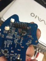
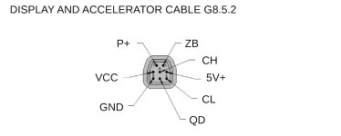
If you connect VCC+ with GND, the controller turns on in BESST mode.

If you connect VCC+ with GND via resistor of 1 ohm for a few seconds, the controller turns on and off.
 
Last edited:
If you connect P+ with GND, the controller turns on in BESST mode.

If you connect P+ with GND via resistor of 1 ohm for a few seconds, the controller turns on and off.
Interesting. With the UART motors, connecting P+ to GND burnt out the controller. Courtesy of the eggrider display. 😩
 

Attachments

  • DC177B05-AD5A-4EF4-A2B4-BDF9A620E842.jpeg
    DC177B05-AD5A-4EF4-A2B4-BDF9A620E842.jpeg
    606.6 KB · Views: 23
Sorry, not P+ but the terminal called VCC or KEY.
You recognize it because it is the only wire with voltage when the controller is off.
 

Attachments

  • MotorDisplayConnector.jpg
    MotorDisplayConnector.jpg
    46.2 KB · Views: 13
Last edited:
Hi CiDi, Did you have any success changing parameters with the can analyser on the 46.2 firmware?
 
Hello,

I am trying to modify the speed limit using arduino and can bus shield. I am collecting data but the identifiers are different.

For example I have 0xBE for controller parameters, where the speed limit, wheel diameter, wheel circumference is signaled in 6 byte data. This is 0x2F8 in the github guide. I notice that is 4x the hex value that I have. Same holds for display, in my case it is 0xC4, in github it is 0x310.

I would appreciate if you could guide me on composing a message that I can send using Arduino.
 
Hi CiDi, Did you have any success changing parameters with the can analyser on the 46.2 firmware?
I can also make the modifications with the can analyzer, but only those of the levels, the same ones that you can modify with BESST PRO, the other modifications it does not accept.
 
The EBike modular DIY electronics (EBike / EScooter modular DIY OpenSource electronics and software), is featured as the Project of the Week on the Python on Microcontrollers Newsletter.

So, I am being riding my EBike, and here is a picture of a full day riding but with a lot of mud:


I have some good news:

1. Wireless communication between the EBike board and display: There is a new Python version (CircuitPyhton) that implements wireless communication between the ESP32 boards - I already tested. This means the display and the EBike board do not need anymore to have the UART communication, so that is less 2 wires to connect. The display only needs 2 wires from the EBike board: 5V and GND (or it can have a battery and be fully wireless - but I do not plan to do this).

2. Unit tests on the firmware: I got the unit tests on the firmware, using PyTest - but on another smaller project using the same ESP32 board. I will bring the unit test to this project and the firmware quality will improve!!
 
Just got word a few moments ago - apparently the Luna Cycle "V2" controller is now available for purchase separately. ...provided you purchased an X1/X2 bike and have authorization from Luna. But in theory, this would replace the 'crappy' X1 firmware variants and locked down bafang controllers with a programmable bluetooth VESC based version.

Price is a bit steep at $350. But you need a $120-$150 BESST just to program firmware and some limited options, anyway. So looking at it that way, the V2 controller is almost a bargain!


On my Dengfu E10 frame, there is a button switch specifically to turn on the EBike. I connect this switch to the battery JBD BMS that has a specific connector for a switch like this. The JBD BMS switch is very important, because it switches the power on/off but in a safe way, avoiding sparks that would damage the contacts and the electronics.

As I am right now installing the VESC + EBike/EScooter board on my Xiaomi M365 stand up scooter, I also need that button switch but there is no such thing on the M365 scooter (well, there is but can not be used on the BMS). I came up with a solution that may be useful for everyone that uses a JBD BMS on his EBike/EScooter:

What: a small DIY board that automatically switches ON the popular JBD BMS, effectively switching ON the EBike/EScooter, when there is motion / vibration. Automatically switches OFF the BMS after a timeout without motion, like 20 minutes (configured).

Avoids the need to install a mechanical switch and also adds the safe timeout that automatically switchs OFF the EBike/EScooter.

Project page repository with all information: GitHub - OpenSourceEBike/Automatic_Switch_Anti_spark_JBD_BMS: A modular DIY automatic switch anti-spark using JBD BMS

Features​

  • Switch ON the EBike/EScooter by shaking: JBD BMS switchs ON when there is motion of the EBike/EScooter.
  • Automatic switch OFF the EBike/EScooter: JBD BMS switchs OFF after a custom timeout like 30 minutes, when there is no more motion.
  • Ultra low power: espected to use only 0.007 watts when JBD BMS is switched OFF (will take 8 years to discharge a 500Wh battery).
  • Cheap and easy to DIY: costs 5€ in materials and needs only soldering 8 wires.
  • Wireless communication with other boards (planned, optional): an EBike/EScooter main board can communicate by wireless and switch OFF immediatly the JBD BMS.
board_05.jpg

board_01.jpg

schematic.png
 
@CiDi Regarding Innomaker and setting the Speed limit via canbus.

I Have a M510 which was broken, after i have received it back from repair it had a 25km/h speed limit. So itried the method from cidi with the custom cabling via the usb2can and innomaker.

for me the id seems to be different. I looked for the C4 09 D0 01 (part of the Dataframe that represents the 25 kmh and the 29 inch wheel size) in the Datastream. I thought i need to press the speed limit info on the display, so that the data is requested by the display, and i can sniff the dataframe.

So I found an id: 0x82F83203 with the data 0x|C4 09 D0 01 08 09 00 00 in it. this seemed to be theo one for me, when i tried to set it to the value: 0x|70 17 D0 01 08 09 00 00, which should just change the speed limit to 60kmh, the controller is not taking over that value. When i sniff the communication again afterwards: The value of 0x82F83203 is still the same old one.

Then I found the information in this thread, that this method only works with FW 46.2.

Can anyone explain how I can install that FW on my controller with the usb2can? Is it even possible to do it with the M510?

Any feedback welcome. It is so annyoingly slow with the 25kmh speed limit and no fun to ride.
 
I just built and documented, on my Xiaomi M365 stand up scooter, the same I did on my EBike with Bafang M500 motor - now it is unlocked, runs faster and has higher motor torque!!
I use the VESC to control the motor + a simple DIY EBike/EScooter board. So yes, using VESC + a DIY EBike/EScooter board, is being work very well for me and is proved to work for any EBike and any EScooter, with any kind of motor!! -- my next EBike will have the Bafang M820 motor, I am waiting to do just the same on it.
OpenSourceEBike.github.io

Some images. Everything installed in place:
1682278817417.jpeg

The DIY EBike/EScooter board:
1682278816298.png

The DIY EBike/EScooter board schematic.
1682278871190.png
 
I built another EScooter using a VESC + the DIY EBike/EScooter board. This time it is only a throttle and brake sensors, can't be simpler. Anyone can use this to drive ANY motor, like any Bafang motor!!
And as we know, VESC is popular and high performance OpenSource motor controller. We can buy it in many online stores like in Aliexpress, and there are small ones of 2kW up to big ones of 20Kw or more.
VESC is able to drive any motor because it has a motor auto detection feature. On this scooter, I installed a 80V 22S battery, and I did ride at max high speed of 50km/h, while with the original battery and motor controller, I only got 23km/h (I am heavy: 100kgs).

If anyone want drive any Bafang motor, this is the bare minimum, throttle + brake sensors EBike/EScooter:

1683641294176.png

So simple this DIY EBike/EScooter board:

fiido_q1_s-2023.04.23-01.png

fiido_q1_s-2023.04.23-02.png

And when I did the very first test:

1683641393840.png
 
I'd like to ask a question and get some advice about M600 noise. I've had mine for about 3 years. When I first got it, I thought it was way too noisy. About a thousand miles in, I installed the Luna M600 silent PEEK gear. This got rid of most of the loud noise and I was, and am, very pleased with this improvement.
Still, things could always be better:) The noise it currently has is a fairly high pitched noise. It occurs at most, but not all, RPMs and loads. Before the gear installation, this was only really heard when cutting power as the motor winds down as it was masked by the gear noise.
Does anyone know what causes this noise and if there's anything that can be done. It's not clear if this is a mechanical noise or possibly an electronic sound. I've read about "coil" or "winding" noise but have no clue if this is what I'm hearing.

Thanks for listening.
 
Hi.

Does somebody know the component (CI) inside the throttle, to check his characteristics ? i can't read it.
It is a component supplied by + 5V and who return +- this power supply (around +- 0.5 V it's seem ?), Depending on proximity of an piece steel. I use throttle for walk mode with limiting mechanicaly the stroke to have +- 4 km/max, but with the M510 and his (pleasure) quicker power increase, it's difficult to use it, i want to built an throttle with 4 km/ on original full stroke
 
It's a linear hall effect sensor. You can limit the speed by placing a resistor divider (or trim pot) in line with the signal line. My BBSHD has a "walk mode" button. The M510 may have a similar feature but I don't have the manual for that model.
 
Back
Top