Build your own CD battery tab welder for about $100.00+-

Here's a caution by Bill Dube against using CD on A123.


http://www.nabble.com/battery-tab-welding-td15258522.html

The inverter welder outputs a square pulse. A capacitor welder puts out a pulse with a long tail. Once the nugget is molten, you want to cut off the current immediately. The area under the "tail" portion of the curve on a capacitance welder heats the crap out of the cell terminal.


And anyone thinking of using contact springs or conductive paste for their battery interconnects should pay attention to this comment by Steven Ciciora.


Early versions of the Killacycle (using boulder cells) were not reliable until the battery manufacture supplied sub modules with copper braid (inverter) spot welded to each cell. Bill tried several soldering techniques, pressure contacts, etc. with various levels of failure.
 
Today I wanted to test my new 8FARAD KOLE audio cap using my 2 huge SCR's(ST230S) 230A/6000Apeak/ 10ms.
2 in parallel will withstand 12 000A/10ms if needed .
They did not fire! I tried 5V and even 12V directly from a cube power supply and power tool battery.
Any idea why? I got them on ebay for £10 each.
here is the datasheet:
http://www.irf.com/product-info/datasheets/data/st230s.pdf
Yes, there is a hole in 0.4mm(0.016 inch)copper sheet when fired at 15V.
Now I'm going to put together array of 24 mosfets and 6 mosfet drivers to make a super powerful switch so I can control the width of the pulse and make my super dual pulse/1cap variable CD welder.
Another simple and not really mine idea is to short the cap after the first SCR switches on using second SCR. For example after say 8ms(variable) and not use any mosfets, but 2 SCRs.
What do you think?
 

Attachments

  • test setup.JPG
    test setup.JPG
    38.4 KB · Views: 6,019
  • test setup strip copper.jpg
    test setup strip copper.jpg
    42.2 KB · Views: 6,137
By shorting the cap with the second SCR, you can terminate the pulse. There are several arrangements to do this, some using an inductor. In the 'old days', this is how they used SCRs to make inverters and motor controllers.

No clue why they won't fire. How are you feeding the gate?
 
I tried switching on with 5V+ on white wire and 5V- on red and even 12V from a power tool battery both ways. With 12V it draws 1.6A one way and in the other direction I only did a short pulse because I didn't want to destroy them and it took a lot of amps(sparked) so not a good idea to even wait and measure. ( I know....not a very scientific way)
I attached SCR's lead to - on the cap.
 
I'm still a little foggy on the proper way to trigger a SCR.
If my ghetto-cad drawing is right, you'd touch the white wire to the anode of the SCR to make it fire. The red wire goes to the cathode. I'm not sure why they have the red wire like that.
I would be safer to put a resistor or resistor/capacitor paralleled in series with the gate to limit the current, but at low power you can just touch it directly to the anode.
 
Nemo- I'm very confused: in one place it looks like you are saying that your SCR's aren't firing, but in another it looks like they are???? Can you clarify that for me?

OK, assuming that they aren't firing:

It is possible that the SCRs weren't any good in the first place ( eBay can be like that, unfortunately.) and there is nothing wrong with your circuit.

I'm going to put the following in the simplest terms, not because I think you need it, but for the benefit of others that might be less knowledgeable about electronics (including myself ;) ):

Try this:

Take both SCR's out of the circuit and separate them to test individually. Hook up an ohm meter to see what the situation is between the big red wire and the metal body/lug. with no power applied anywhere. It should be somewhere between a couple hundred megohms and 'infinite' meghoms. (the meter may 'dance' around a lot, but should stay in the megohms range) If there is little or no resistance the gate is fused closed and the SCR is trashed.

Then, with the ohm meter still connected, try triggering by connecting just a regular 1.5V alkaline battery with the positive + going to the white wire and the - negative going to the big metal lug of the SCR. With power applied to the gate, the resistance should go down to 0 (or near 0).

If it doesn't work, try it with 2 alkalines in series ( or a single 3V lithium primary battery...to trigger the gate.

If THAT doesn't work, try + to the white wire and - to the little red wire.

And if none of that brings the resistance down to '0', the gate is 'burnt out' and the SCR is trashed.

If the SCRs test out OK, but the system still won't fire, draw up and post a sketch of your entire basic circuit and I'll try to figure out if there is something wrong with it. (Don't include any of the MOSFETS and stuff like that... That will only confuse me. ;) )
 
fechter said:
I'm still a little foggy on the proper way to trigger a SCR.
If my ghetto-cad drawing is right, you'd touch the white wire to the anode of the SCR to make it fire. The red wire goes to the cathode. I'm not sure why they have the red wire like that.....

Boy, I can't believe that I'm offering YOU electronics advice :shock:

While I can see how your 'ghetto cad' circuit might work, it is completely different from any SCR firing circuit I have seen:
Everything I have seen has a completely separate (or at least isolated) supply to power the gate. I'd be afraid that using the main power supply to trigger the gate, even through the R/C circuit, would possibly zap the gate with over voltage and/or over current, plus maybe even cause some kind of weird pulse feedback cycling.

I'm glad to see that you are confused by SCR gate connections too... I've got about 5 different kinds of the big ones around here now, and every different model triggers differently. The data sheet may give a hint as to how thay are supposed to be hooked up, but I always have to test a new model as I laid out to Nemo above to figure out how they really work.

And some, but not all, work two ways: Some work with the + trigger voltage going to the gate input and the - going to the 'big metal lug' , and will also fire with - going to the gate input and + going to the 'big red wire' and/or the 'little red wire" (or blue wire in the case of a couple of my really big ones).

And I have at least one that 'the big metal lug' is apparently actually the cathode and 'the big red wire is apparently the anode.

When it comes to these darn SCRs, I absolutely have to follow the advice in your tag line:
"One test is worth a thousand opinions"
 
Thanks for all the help. I did all the tests described above and I think my SCR's are faulty. (gate is 'burnt out' )
Simply nothing will switch this on! The resistance is 2.5Mohm but applying any voltage +/- on the gate (1.5 and 3V) doesn't do anything.
I'll write the seller for the replacement or refund.
Now I'll concentrate on mosfet switch. It will take me some time since I need to import the best mosfet on the planet irf2804 (2.3mohm,40V) from the USA.
If any of you are interested in 25 of them let me know. The price is only $1.8/each plus some small shipping within the USA. The order would be for 50(minimum quantity for this price) package is D2-pack.
3rd item from the top, here:
http://www.componentsuperstore.com/Store/SearchResultKeywords.aspx?Keywords=irf2804&SearchType=Keywords&CategoryName=40203050000&ManufacturerName=INTERNATIONAL+RECTIFIER
I would pay for the second half and shipping to the UK.
Let me know !
 
I have some progress here(8F 24parallel mosfet based CD dual pulse welder)
The super 9A peak mosfet drivers TC4422 are on the way to me from the USA, 4x 555 timer works as planned.See the picture.
I'll add 2 more 555 timers and all the logic will be ready.
How will it work?
First waveform shows delay(10ms) than second waveform shows first 1ms pulse followed by 100ms pause and finally second welding 10ms pulse.
Pulse width is changeable, of course!
The pause will be useful when yet another 555timer will disconnect my 20A power supply from the 8F cap.(for about 2 sec =enough time to take off the electrodes after the weld)
The last 555 timer will block diode in optron so no one can fire again for about 8 sec (charging the cap in my case takes 6 seconds plus 2 seconds for welding / resting time).
Quite simple.
The bad news is that the mosfets IRF2804 in my previous link are suddenly twice the price a week ago! Simply there is not an option to buy 50 but 800 for the lower price. So it is getting more expensive.
Well, bad luck here.
anne 021 file: schematisc of the working 4x 555timers. 2 more will be added, 24 mosfets for power stage, 8 mosfet drivers, cap 8F, another mosfet that will connect and disconnect the power supply from the 8F cap
 

Attachments

  • anne 021.jpg
    anne 021.jpg
    116.9 KB · Views: 1,872
TO RHOON:
Something is wrong with the PM system here, and my reply to your PM is stuck in the outbox.
Since you may be about to do something that is kind of dangerous, I'll post it here and hope you see it in time.
-------------------------------------------------------------------------------------------------------------------
I don't think that capacitor will do the job by itself. four or five of them in parallel MIGHT. I wanted to try some of those lower voltage 'super-caps' but haven't gotten around to it. The lower the voltage the more farads you have to have, so at 6V, even with the better ESR of 'real' caps, I'm guessing you would need at least three, if not eight farads total.

The short answer on charging the 6 V capacitor with a 12 volt power supply is that you can't..... The capacitor will literally explode if you try. There are some electronic circuits you could build to lower the voltage, but that is a little complicated and impractical.

Sorry to say, but I'd give up on the whole idea of using 6 volt capacitors.

Even if they contain enough power to do the weld, it is just impractical: Charging one without blowing it up would require a highly regulated power supply that puts out no more than 6.3 volts... preferably 6 volts or less. You COULD use a computer power supply's 5 volt line to charge it, or something like this:
http://www.allelectronics.com/cgi-bin/item/PS-523/480/5_VDC_2_AMP_SWITCHING_POWER_SUPPLY_.html
but you can't even use a cheap 6V car battery charger because their actual output is over 7 volts, which would be dangerous pumping it into that capacitor.

Sorry i couldn't tell you what you wanted to hear.
 
Today I got 2x 6 farad car caps in the post. It means 8 caps in parallel from power acoustic , total of 12 farad to play with.
The 24 mosfet swith is working fine.
I abandoned the idea of using 1x 8farad cap after trying it, too week.
Then I tried 3x 1.5 farad, better, could just about spot weld nickel 0.3mm to 0.3mm of nickel. Too week.
Today I might try 12 FARADS and 8 caps in parallel.
I hope I don't blow the mosfets!
Will post the results later. Cheers to all. I didn't give up! It just got more expensive :)
 
That should be more than enough, Nemo. My 5F Power Akoustik does the job on .005 nickel tabs acceptably by itself .... Although I do now have the 1.5F Volfenhag cap in parallel too... The combination is just about 'perfect' for doing nickel to nickel or nickel to steel. I only use the dual pulse with the higher voltage setup to weld copper....

I'm just wondering if you have been unlucky with crappy ESR caps, or if there is some flaw in your setup otherwise that is causing power loss.????

At what voltage are you charging? I find that 14.5 -14.6V (My higher current PS's limit) to be about twice as effective as 12 - 13.2V.

Well, good luck.
 
I didn't finished my setup today !, No time now ! Sorry!
So the result will be posted here with the photos on the 10th may when I get back from my travel. It is a dual 24 mosfet based welder with 2 independent pulses and changable delay, with huge cables, huge electrodes and 4.6kg of caps. see some photos here:
http://picasaweb.google.com/pavelnemo/NEMOCDWELDER2008?authkey=zpOHQxeV_zc
 
I found this video on youtube

its sodering to the ends.. but its a nice clean job!

http://www.youtube.com/watch?v=vkDgoXikI_8

Have we figured out how to get the tabs for a123's?

thanks
Steveo
 
Finally: better electrodes!!!! :!:

I scored some 3/16" X 8" Elkonite® rods off eBay. There are several different formulae for Elkonite, and the seller didn't know which particular ones these were, unfortunately, but they all are basically Copper-Tungsten in varying percentages, some with a few other metals as minor alloying constituents.elkRod.jpg

Previously, the most successful electrodes I had tried was that plain old copper heavy grounding wire as reported in the early pages. I tried Beryllium-Copper, which gave nice, solid welds, but the electrodes stuck to the work very badly and needed re-sharpening after every weld because of having to break them free.

Tried 'pure' tungsten... Again, nice welds, but again, major tip problems: They didn't stick like the BeCu... The tips just 'blasted off'tungsten.jpg

Tried another couple of metals with dismal results. Never did get the chromium copper that I wanted to try. Found the material at a decent price, but shipping would have been $50.00 and ordering was a hassle too.

And of course, the plain copper needs re-sharpening all too often too.

But finally this Elkonite stuff is durable and gives good welds in all of the conditions I have tried it so far.

The one negative is that it has a lot of resistance, so you need to have the wire/cable attached close to the tip. If you connect it at the far end, after about 5 quick welds it gets uncomfortably hot.... and having the connection that close to the work is a bit unwieldy and could be a little dangerous.

Fortunately, there is a (fairly) simple solution!
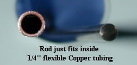
It just so happens that the 3/16" Elkonite fits just about perfectly inside 1/4" flexible copper tubing:fits1.jpgfits2.jpg

And you make something like a 'pencil' out of it:
pencil.jpg
First, I polished all the oxide off the Elkonite rod; and while it could be done by hand, or an electric drill, I chucked the rod into my lathe; turned it on to a couple hundred RPM and sort of 'spun fit' the copper tubing onto it... this method has the added effect of grinding off any oxidation on the inside of the copper tube for better electrical conductivity.
It was a pretty tight fit, but once the tube was on the rod, I fed it through the lathe chuck an inch or two at a time and really tightened the chuck hard to provide a strong crimp, just to be sure.

Grind the tip to a point (as in the photo above) and clean up the tool marks off the outside of the assembled electrode and you are almost ready to weld.

But a little insulation/handle is nice. I just happened to have some old ceramic tubes that I got off of (I think) American Science and Surplus several years ago for an electric kiln project I never got around to starting... Just about the right size for a handle, and the hole down the center is a perfect fit:electrode.jpg
Now I can connect my welding cables to the end of the electrodes where they are safe and out of the way, and have even better conductivity overall.

The quality of the welds on Nickel tab material (at 14.5V)and .005 Copper (at 23V) to steel is about like that with the plain copper electrodes:View attachment 3
But for the first time I can crank up the voltage enough to weld .008" copper to steel..... Yeah, I could do that before, but at that voltage the copper electrodes welded themselves to the work too, and when you pulled them off (with some difficulty) often the tabs came off the battery too.
weld2.jpg

Now it works great!.

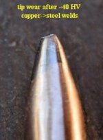
Tip wear is decent; Still have to sharpen several times if you are building a big battery pack using copper tabs, but at least 5 times better than with plain copper electrodes.:tipwear.jpg
---------------------------------------------------------
A few other new details:

1: Previously when welding the .005 copper,by the time I cranked up the voltage enough to weld it, I was puncturing the copper and just leaving sort of a thin halo of a weld around a hole in the copper, and sometimes 'blasting through" the material below too :shock: . The electrical connection from such welds was OK, but very little shear strength. The tip diameter that worked fine with Nickel and gave excellent welds that you could cluster close together was just too narrow to work well on the higher voltages and dual pulse necessary for copper. So, now for copper, I'm using about .075" -.085" tip diameter instead of the about half that I was using before.

2: Pretty much no matter what voltage you use on this simple setup or similar home-built CD welders; whenever welding copper, if you put both electrodes on the copper strip/sheet, you don't get a great weld.... You might get ones that will work, but they are far from strong. (This after all is a form of RESISTANCE welding, and there isn't much resistance if it the welding path is just mostly along the copper itself. So, for stronger welds, if at all possible, put one electrode on the work (IE: steel battery can) itself. That provides a better resistance weld path and gives much stronger welds.

3: I had noticed it before, but it wasn't highly obvious until I started using these Elkonite electrodes: The positive electrode "sticks" much more solidly than the negative electrode. When welding Nickel tabs at lower volts, it is insignificant, but at higher volts it can get to be an impediment. I need to test it further, but it seems that the best method of welding copper is to use the negative electrode with an about .075 tip diameter on the copper strip/sheet and a significantly thicker point on the base material.... as large as you can get to fit would be fine... In fact, some of my best results last night were from flipping the electrode over and using the non-pointed end as the contact on the base.

And one last thing for now: I found a couple of different kinds of connectors at Lowe's or Home Depot in the electrical department. A little more 'elegant' and conductive than the galvanized cable clamps recommended originally and a lot less trouble, if somewhat bulkier than the ones I machined out of some copper rod previously:conn1.jpg

Umm... Looks like I've run out of attachments allowed for one post: I'll finish up in another.
 
OK, Last little bit for the moment:
conn2.jpg

I think the connector in the photo in the previous post cost about $2.25 or so each, and the smaller ones as pictured directly above were 2 in a package for about $1.75 or so.
If you are using 10 Ga wire for your welding cables and electrodes under less than 1/4" / 6mm you could cut off the tab and just use the clamp part on the smaller one to make a neater 'package'. Or leave it on for bigger cables and solder or bolt them through the hole .

The larger clamp above works with 4Ga cables ok.... But I had to 'dremel' out a little material to get the 1/4" tubing of the electrodes to fit too..
 
RLT I built a copy of your battery tab welder II and am currently charging the caps with my 12 volt ps turned up to 14.2 volts. I am using 8 Guage wire from a car audio store to copper electrodes. I am not getting good spot welds and I can't figure out why. My welds are more like "tack welds" which tear off easily. I would like to try a higher voltage but my ps I bought from ebay has not arrived and I am beginning to think it never will :cry: I have tried welding with the voltage display and lights connected, and with them disconnected and did not notice a difference in the quality of welds. I have soldered my 8 guage wire to the electrodes using a torch to eliminate a resistance problem there, and then I shortened my electrode wires but still no change. I tried several different connections to my 350 amp rated scr with no improvement. I hope you can help me figure out what can be done to improve my set-up because so far I am dissappointed and think I may have wasted my money. :cry:

-----Robin
 
Hi Robin-

Sorry to hear you are having problems with it.

Need to know more information.

What kind of capacitor(s) are you using?

What kind of tabbing material?

When you say you are getting "tack welds"... Look at them closely. When you separate the material, is there any of the tabbing material left behind?

Photos of everything would be helpful in diagnosing the problems.

But just guessing at your limited description, I'd say there is either a bad connection somewhere, or the capacitor is not good enough: defective or just a really lousy ESR.

Oh.. If you are using Car audio capacitors, don't go over 16.0V if you get that new power supply... They lie when they rate them at 20-24 volts. Every one I have tried has vented if I went over 16V.
 
Amazing thread! I wish I saw it earlier. A few questions

- What if capacitors are replaced by SLA batteries? This is a total newbie question, so clue me in if this makes no sense. From interenet,
- SUV batteries provide up 1000A cranking amps at 7V (for up to 20 sec).
- Spot welding is in 100-400 Ws energy range, 1-10ms duration. 1000 amps at 7V for 10ms is: 1000*7*0.01 = 700Ws.
- Or looking by internal resistance, Optima Redtops have 2.8 miliohm. How does that compare to supercap ESR?
 
Another idea question is would this MOSFET work instead of SCR?

IR1324 1600A pulse current, 24V, $5
http://www.irf.com/product-info/datasheets/data/irf1324s-7ppbf.pdf

The reasons to use it are:
- Turns off by when you tell it, so can control pulse duration/ do two pulses
- Easy to drive from digital gates if decide to add MCU control/adjustability

Any reason this wouldn't work?
 
Some people have reported using car batteries with success, but I have my doubts. They don't release their energy as rapidly as a capacitor does,,, It kind of ramps up... Which makes things overheat, which leads to damaged batteries.

I think. I don't know for a fact. Give it a try and report back ;)

You CAN use Lead Acid batteries instead of, or in parallel with a battery charger to charge the capacitors more quickly though. I haven't yet, but maybe I ought to give it a try when I start building the next packs for my eBike, which will be soon. I get kind of tired of waiting for my little 3A lab PS to charge the higher voltage bank in between welds when I'm doing hundreds of them in a row.

As far as using MOSFETS... Nemo and a few others are trying it. That route is a little more complicated than I want to bother with, personally, and I'm not sure how successful they have been in actually producing good welds. I just don't know enough about designing circuits to want to get into it, and I'm 95% satisfied with the way my current setup works, so I'll leave that up to you guys.
 
Yippie!!!!
I finally found some molybdenum that I can try for electrodes for welding copper that I can afford:
http://www.torreyhillstech.com/mowshoponline.html?gclid=CKj69OT175ICFRUvlgod91hF3w

Ordered a piece of 3/16 inch, So, I' should be able to make the copper tubing "pencils" like I did with the Elkonite as described above.
I did see their website a couple of months ago, but they didn't have a shopping cart or anything that gave an idea of what was available for what price.

It's funny, They have an eBay store too, but as many times as I have searched eBay for Molybdenum, it never turned them up.

Oh, and the guy that I bought the elkonite rods from has another auction up. I was tempted to buy the last of his stuff, just to have, until I ran across the moly rod.
If any of you guys are interested:
http://cgi.ebay.com/TUNGSTEN-COPPER-ELKONITE-RODS_W0QQitemZ200216825878QQihZ010QQ

Now if I could just find some .005 (or better yet; .007 or .008 ) half inch wide nickel strip in rolls (for building my 32650 LiIon packs) rather than the short pieces from Sunstone Engineering, for reasonable prices at under a ton at a time, I'd be a happy camper.
 
RLT My capacitor is the Power Acoustik 5 farad cap you recommended. I am welding with Sunstone engineering .005 nickel strip. I do seem to be getting adequate spot welds on aa size cells, but when I try to weld c-size cells I don't seem to be getting enough heat. On the aa cells there remains a little nickel material at the weld spot when torn off, but not on the c-size cells. I have tried many different old ni-cads and NiMH cells, so I don't think it is just the particular cells I am experimenting with. I would like to try 16 volts but I have never received the unit I bought off ebay. I will post pictures of my set-up as soon as I get time and can figure out how to post pics.

-----Robin
 
Try cleaning your C cell terminals with sandpaper or steel wool (be careful not to short them if you use steel wool.) If it will weld AA's OK, it should weld C cells even better.

Unless perhaps your C-Cells have non-steel 'cans'... Unlikely, but I guess possible. Check them with a magnet to be sure.
 
Thanks for all the really useful stuff posted on this thread. Having read it from end to end I'm all set to build myself a welder. I've ordered 64 10Ah Headway LiFePO4 38120 cells, which come without tabs, so am planning on building my 16S, 4P pack up by welding strips across four cells in a row to build the 4P units, then adding strips to connect the packs into the odd shape I need to fit inside my electric motorcycle frame.

I've managed to buy 15 off, 97,000uF, 20V capacitors for under £10 (less than $20). They have a nice low ESR, so should give me nearly 1.5F at up to 20V, which I reckon should be OK going on the experience on here. Rather than opt for an SCR trigger, I think I'll go for a bank of high current FETs, so that I can control the pulse width better. I may look at a double pulse system, as this should be really easy to do using FET control. It looks like the first pulse only needs to be strong enough to clean things up, with the much bigger second pulse doing the real weld. With luck I think that this should work OK from one capacitor bank, provided the pulse width of the first pulse is kept pretty narrow.

Luckily I have a stock of fairly hefty FETs, so will start playing and see what happens. All I need to get is some wide nickel strip from somewhere affordable, plus some electrode material.
 
Back
Top