C Cab Hot Rod Power Advice

fechter said:
That looks a little easier to follow. One nice thing is your dc-dc will also protect against shorts. It will be hard to burn up a wire on the 12v side.

Thanks, fechter.

The fuse panel may still be overkill and unnecessary, but unless there is something wrong with my diagram such as the need for a relay or using incorrect fuse size this will begin the wiring process.

I still need to determine what the different circuits need for fuses.
 
It's very handy for troubleshooting later if you get a short in something. Pull fuses until the short clears to narrow down the problem. Or the fuses actually blow.
 
fechter said:
It's very handy for troubleshooting later if you get a short in something. Pull fuses until the short clears to narrow down the problem. Or the fuses actually blow.

Good to know thanks
 
Not much done today. XMAS lights to put up.

Got the body off so I can work on the wiring easier.

DSCN5253.JPGDSCN5254.JPGDSCN5252.JPG

The next step is to sit and plan how it all goes together.
This is the preliminary positioning of the terminal blocks/converter.
By doing it this way, only an uncoupling of the rear lights should allow body removal.
The two, wire bundles won't be used.
I'm already visualizing the next, roadster body.
 
As I learn . . .

I'm learning about relays. When, why, and how to use them.
I checked the wattage and amps of the sealed beams I'm using and the result is: 75/55 watts (High/low beam I presume)

That calculated out to 6.25 amps on high beam and 4.58 on low beam. Times two for two headlights = 12.5 amps, 9.16 amps. Not sure if the whole circuit should be fused at 10 amps. I understand that the fuse should NOT be greater than the total load.

The rear lights are 6" LEDs with minimal amp draw.

So as of this post anyway, you will see I have added a relay for the headlights. If I have done it correctly.

The 5-gang panel toggle switches are rated for 20 amps each so should be OK for (on/off)
But for the simplicity of switching from high to low, I think I will be using a separate switch with a 5-pin relay.

Maybe an 'old-school' floor switch.
https://www.homedepot.com/p/Headlight-Dimmer-Switch-DS72T/308424145?source=shoppingads&locale=en-US
 

Attachments

  • fUSE BOX WIRING - WITH RELAY.png
    fUSE BOX WIRING - WITH RELAY.png
    182.1 KB · Views: 1,221
Oops, forgot to add in the battery cut-off switch.

Need that because the circuit breaker on the battery is inaccessible when all is done.
fUSE BOX WIRING - WITH RELAY.png

Not sure what kind yet. Just looking over the many options out there.

Maybe something as simple as this:
Battery Cutoff Switch
https://www.harborfreight.com/battery-cutoff-switch-63425.html?ccdenc=eyJjb2RlIjoiNDk3MDQyOTAiLCJza3UiOiI2MzQyNSIsImlzIjoiNi4yOTEifQ%3D%3D

Or more elaborate like this:
https://www.ebay.com/itm/174313105676?chn=ps&mkevt=1&mkcid=28
 
The simple switch is closer to what you want. The problem is the inrush current going to the controllers when you turn it on. It will make a big spark. If the switch is hefty enough, it will survive this. The solar circuit breaker style in your battery pack is the best.
I've seen setups that use something like bicycle brake cable to remotely operate the lever on a breaker.
 
Apparently there is a version of these cutoff switches that can be setup to use a precharge resistor if you need to
https://endless-sphere.com/forums/viewtopic.php?f=14&t=114290#p1690283

though I've used the t-handle harborfreight switch for years on SB Cruiser without a problem, 14s (58v full) on dual-controller setup with a DC-DC and built-in charger and stuff that has significant capacitance (and makes a hell of a spark on the Anderson SB50 contacts if I connect the battery with the switch on).
 
amberwolf said:
Apparently there is a version of these cutoff switches that can be setup to use a precharge resistor if you need to
https://endless-sphere.com/forums/viewtopic.php?f=14&t=114290#p1690283

though I've used the t-handle harborfreight switch for years on SB Cruiser without a problem, 14s (58v full) on dual-controller setup with a DC-DC and built-in charger and stuff that has significant capacitance (and makes a hell of a spark on the Anderson SB50 contacts if I connect the battery with the switch on).

fechter said:
The simple switch is closer to what you want. The problem is the inrush current going to the controllers when you turn it on. It will make a big spark. If the switch is hefty enough, it will survive this. The solar circuit breaker style in your battery pack is the best.
I've seen setups that use something like bicycle brake cable to remotely operate the lever on a breaker.

Thanks so much for the feedback. I've read through all that you have written and the links.

What that has made me think to do is this:
https://www.ebay.com/itm/261979680916?hash=item3cff34b094:g:DzMAAOSwcLxYK3wC

The battery uses a 63A breaker. If I go this route should I use a 60A or the next higher @ 70A?
I'm thinking I should use the 60 A.

This would solve not only the disconnect issue but the 'panel mount' version will solve where to mount the breaker. And it would not stick out like a sore thumb!

What do you think? Doable?
 
That breaker looks good. If they come in 70A, I would go for that, but 60A should work. You don't want it to trip unless there's a short.
 
fechter said:
That breaker looks good. If they come in 70A, I would go for that, but 60A should work. You don't want it to trip unless there's a short.

Thanks fechter. I can get it in 70A for the same price.

Can you give me a short explanation why 70A vs 60A? Remember the battery is using a 63A
 
Just_Ed said:
fechter said:
That breaker looks good. If they come in 70A, I would go for that, but 60A should work. You don't want it to trip unless there's a short.

Thanks fechter. I can get it in 70A for the same price.

Can you give me a short explanation why 70A vs 60A? Remember the battery is using a 63A

Maybe I answered my own question. Regardless of the higher amps on the cut-off/breaker, (70A, 80A, 90A, etc.), the battery breaker at 63 amps will be the 'protector' of the circuit. Do I have that correct?
 
The breaker is there to protect the power source from an external short. So it has to be high enough current to allow full continuous operation at whatever the max current of the system will be, but it has to pop if a condition occurs (shorted wires, etc) that could cause a fire in the wiring.

Fuses and breakers are intended to protect the sources and the wiring from the source to the usage-point, from conditions that would cause damage, fires, etc. So they have to be sized to allow normal operation, but not allow the damage.

The BMS and such inside the battery should already be able to protect against other things like overcurrent.
 
Just_Ed said:
Maybe I answered my own question. Regardless of the higher amps on the cut-off/breaker, (70A, 80A, 90A, etc.), the battery breaker at 63 amps will be the 'protector' of the circuit. Do I have that correct?

Right. If you have two breakers in series, the weakest one will trip first. You don't really need it to be a breaker, just a switch, but these are made to handle the current/voltage you have in your system. As Amberwolf points out, the BMS should trip before the breaker too, but those things can fail and it's always good to have a breaker or fuse somewhere.
 
While I wait for the circuit breaker to get here, I have been playing around with dash configuration.

My latest design with one extra toggle for, ???
Dash Panel -1-2.png

Another Version

Dash Panel -1-2.png
 
No key?

If you wanted to have a key, you could switch the "ignition" line going to the controllers so if it was off the motors couldn't run. Otherwise, just don't park it unattended where someone could drive off with it.

What about ground effects lights? Multi-colored LEDs under the floor pan that light up the ground under the car at night. Not street legal in some places but looks cool at night.
 
fechter said:
No key?

If you wanted to have a key, you could switch the "ignition" line going to the controllers so if it was off the motors couldn't run. Otherwise, just don't park it unattended where someone could drive off with it.

What about ground effects lights? Multi-colored LEDs under the floor pan that light up the ground under the car at night. Not street legal in some places but looks cool at night.

I knew there was a reason for the empty corner on the left :lol:
And an FYI for those that aren't paying attention. No the dash isn't vertical. WHY?
Because the drinks would spill ...boom, boom!
Dash Panel -1-2.png
 
fechter said:
What about ground effects lights? Multi-colored LEDs under the floor pan that light up the ground under the car at night. Not street legal in some places but looks cool at night.

amberwolf said:
ejection seat?

LED's and ejection seat...hmm :idea: I know, a night launch would be awesome.
Maybe NORAD could follow it.
 
The LED lights idea got me curious. I looked for 12-volt Christmas lights.
Found them and now I just need to find a nighttime Christmas parade.
 
I remember seeing an ejection seat handle for sale on eBay one time. Might be fun even if it wasn't functional.
 
nicobie said:
Don't forget the air bags. :lol:
fechter said:
I remember seeing an ejection seat handle for sale on eBay one time. Might be fun even if it wasn't functional.

You guys are not only a great help, but you have super good ideas as well. :idea: :bigthumb:

Airbags...paper or plastic..boom, boom!

Eject button cig lighter?
https://www.ebay.com/itm/174200994321?chn=ps&mkevt=1&mkcid=28
 
Moving right along

The breaker is to arrive Monday and the switches on Wednesday (maybe).

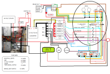
Updated the wiring diagram to add the circuit breaker and now the 12-volt voltmeter as well.
I have wired the breaker on the positive line because that is how the breaker in the battery is wired.
Reminder: the extra breaker provides access to it, whereas the battery breaker is inaccessible once the battery cover is on.

I will have dual voltage readings at any given time. If they are wired correctly.
I have wired the 12-volt meter to the 12-volt socket circuit. I can flick the switch at any time to see what my 12-volt system is doing and/or use the 12-volt socket. Right next to the - EJECT button.
fUSE BOX WIRING - WITH RELAY.png


Also redesigned the dash layout.

The primary power switch is now located on the rear vertical panel behind the switches
Dash Panel -1-3.png

With so much thought going into this wiring, I'm sure to forget or get something wrong.

I'm starting to see the end of this, and the excitement is growing each day, that maybe, just maybe I will actually realize my goal of driving it in a parade or 2, or 3 or ? 🙂... next year.
 
Back
Top