C Cab Hot Rod Power Advice

New problem

I want to have a 'battery on' warning light. I've looked throughout the internet and haven't found any of the common dash warning lights that are 48 volt powered.

Is there an option without having to install a second dc-dc converter to use lower volt lights?
I don't want to fire up the main converter just for one light.
 
If they use LEDs then all you need to do is put another series resistor with the light inside the switch / module, so that the current thru the LED stays the same. Dunno what resistor it has in there now, but current is typically a few mA per LED, perhaps a few dozen. You can use your multimeter to measure the current draw on it, set to 200mA and put the red and black leads on the A or mA hole and ground of the meter, then put the other end of the leads in series with the power to the LED.

We'll just say it's 10mA for a nice round number. So to get that for a "12v" system, they would use 12v / 10mA = 1.2kohm resistor. For 48v to get 10mA, you'd use 4.8kohm resistor. If you use it in series with the existing resistor, the currrent will be lower and the LED dimmer, if you want the same brightness as original you'd just subtract the original 1.2kohm from the 4.8kohm and use a 3.6kohm resistor. If you cant get the value you need, use the next higher one, not lower, cuz less current is better than more. ;)
 
amberwolf said:
If they use LEDs then all you need to do is put another series resistor with the light inside the switch / module, so that the current thru the LED stays the same. Dunno what resistor it has in there now, but current is typically a few mA per LED, perhaps a few dozen. You can use your multimeter to measure the current draw on it, set to 200mA and put the red and black leads on the A or mA hole and ground of the meter, then put the other end of the leads in series with the power to the LED.

We'll just say it's 10mA for a nice round number. So to get that for a "12v" system, they would use 12v / 10mA = 1.2kohm resistor. For 48v to get 10mA, you'd use 4.8kohm resistor. If you use it in series with the existing resistor, the currrent will be lower and the LED dimmer, if you want the same brightness as original you'd just subtract the original 1.2kohm from the 4.8kohm and use a 3.6kohm resistor. If you cant get the value you need, use the next higher one, not lower, cuz less current is better than more. ;)

I did ask, didn't I? :shock: Thanks for going to all that explanation. Because I'm a novice at this I interpret what you are saying as a modification of the breaker/switch. The need/desire to have that light isn't that great.

I have found plenty of 12-volt lights, so maybe that would be the best way to approach this after all.
 
It's not a bad idea to have an indicator somewhere. If for the dc-dc, it would be better to place it on the output side. It makes the series resistor for the LED dissipate much less heat and also tells you the dc-dc is working. Easy enough with battery voltage too, but the resistor will need to be physically large enough to dissipate the heat. For a typical LED, which has a maximum current of 20mA, I'd use a 3.3k or 4.7k, 1W resistor. 1W ones are about 1/4 in diameter. It will get pretty warm.
 
fechter said:
It's not a bad idea to have an indicator somewhere. If for the dc-dc, it would be better to place it on the output side. It makes the series resistor for the LED dissipate much less heat and also tells you the dc-dc is working. Easy enough with battery voltage too, but the resistor will need to be physically large enough to dissipate the heat. For a typical LED, which has a maximum current of 20mA, I'd use a 3.3k or 4.7k, 1W resistor. 1W ones are about 1/4 in diameter. It will get pretty warm.

Two feet forward-one foot back.

Disregard the following. We've been here done this already and this old brain can't keep up I guess.

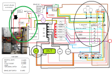
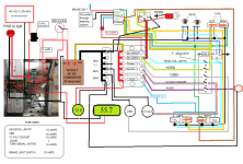
While looking at how to wire in a 12-volt indicator light I found what looks to be an extra positive wire going to the IGN switch then to the converter. Not sure how it got there so not sure what its function is.
3 (red) positive wires where there are only 2 called for.

It's inside the green oval marked with yellow and red. To me, it isn't necessary.


Another thought. I'm thinking I can move the IGN switch to where it is marked in purple.
If I was to use a twelve-volt indicator light on the output wires (just ahead of the proposed new switch location) then I would as you mentioned, know if the converter is on.
Wouldn't this arrangement nullify the need for any added resistors?

fUSE BOX WIRING - extra positive.png
 
Ok, I'm trying to clean this up. Think it's confusing? You should see it from behind my eyes, shock: whoa!!

Unless there is something incorrect I hope this can be the final draft.

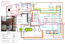
Key to changes in diagram

#1 - The installation point for the 70 amp circuit breaker. Once the vehicle is completed and in drive mode, the main battery circuit breaker will be left on and this new breaker will be the primary on/off for power to the system.

#2 - The is where the key switch was originally positioned. Up to this point, I haven't used a key switch. I shunted the switch wires for both controllers and have been driving it that way with no known problems.

#3 - This is where I intend to wire in a 12-volt indicator light. The light provides a visual warning when the battery/system is left 'on'. My logic is, the power goes to the controllers and the converter via the breaker switch. The amount of time would normally be short. Not much reason to have this 'on' condition unless there was some intent to ready the vehicle for driving.

#4 - The new position for the key switch. The idea is that when needed the power would go directly to the controllers and converter via the new breaker but not past the key switch to the remaining system until the key is turned on.

I hope this helps to see what's-what, and any mistakes I may have made.

Thank you for helping, guys. I wouldn't be where I am without your help.

fUSE BOX WIRING -4-chg's.png
 
Yes, it's getting pretty complex there. I don't see anything that won't work.

The ignition switch is probably unnecessary at it will only turn on/off the 12v loads and won't keep someone from driving off with the car. You could switch the "ignition" lines going to the controllers. That would keep the motors from running but everything else could be turned on.

The relay may not be necessary depending on the amp rating of the headlight switch. Won't hurt to keep it as is.

It looks like you have the brake lights wired. Not sure why there's a ground connection to the brake light switch. I don't think it needs one. There is probably a way to make the brake switch also kill the motors. Normally this is a connection to ground to kill. Some controllers have a "high level" brake input that comes off the brake light wire and kills when voltage is present. This is optional.

Audio systems are generally under 5A. They usually have their own fuse inline with the 12v wire too. If you install a player, you can see what the fuse rating on it is and use something slightly larger.
 
fechter said:
Yes, it's getting pretty complex there. I don't see anything that won't work.

The ignition switch is probably unnecessary at it will only turn on/off the 12v loads and won't keep someone from driving off with the car. You could switch the "ignition" lines going to the controllers. That would keep the motors from running but everything else could be turned on.

The relay may not be necessary depending on the amp rating of the headlight switch. Won't hurt to keep it as is.

Well after all the fuss about not finding the right type 48 volt indicator light, I found one today. It's on order and will be here ????? https://alpinetech.com/alpinetech-8mm-6v-12v-24v-48v-220v-120v-ac-dc-led-metal-indicator-pilot-light-lamp-wire-leads/

So with the 48 volt light, I can go back to plan 'A' and install the light so it shows when power is on with the new breaker. AND, I can move the IGN switch back to where it is supposed to be. I only shunted them for fab work anyway.

I received the new breaker (70A) and the new switches today. The switches are all lighted SPST @ 20A.
https://www.ebay.com/itm/252346785495?ssPageName=STRK%3AMEBIDX%3AIT&_trksid=p2060353.m2749.l2649

My headlights are 75/55 watts, assuming that means high and low beam wattage.
If I used the calculator correctly @ 75 watts, that will only be 1.56 amps per headlight X 2 = 3.12 amps
https://www.rapidtables.com/calc/electric/Watt_to_Amp_Calculator.html

Plus I can't find any amperage for the rear LED taillights. But they should be negligible I would think.
https://www.harborfreight.com/6-in-submersible-led-stopturn-trailer-tail-light-64327.html

So with 20A switches, there isn't any reason for using a relay for the headlights? I'm asking.

Now the instructions for the OOGA horn call for a 30A circuit and a relay. (Negative ground)
I have a 4-pin relay if needed.
https://manuals.harborfreight.com/manuals/96000-96999/96291.pdf (diagram on page 4)

And lastly, I removed the unnecessary ground going to the brake switch.
 
Just_Ed said:
My headlights are 75/55 watts, assuming that means high and low beam wattage.
If I used the calculator correctly @ 75 watts, that will only be 1.56 amps per headlight X 2 = 3.12 amps
If they're 48v headlights, then yeah. No relay should be needed. Current will be four times higher if they're 12v.


Plus I can't find any amperage for the rear LED taillights. But they should be negligible I would think.
https://www.harborfreight.com/6-in-submersible-led-stopturn-trailer-tail-light-64327.html

If they draw the same power mine do (look similar, from amazon)
https://www.amazon.com/gp/product/B07T9DLSLM
https://www.amazon.com/gp/product/B07PKBZGCR
then it's way less than an amp per light even on brightest.

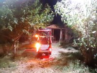
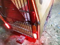
Note however that the "brake/signal" light isn't very much brighter than the "tail" light, so I used two sets of red, one for brake and one for tail, and the amber set for turn signals. (pic at end)

Now the instructions for the OOGA horn call for a 30A circuit and a relay. (Negative ground)
I have a 4-pin relay if needed.
https://manuals.harborfreight.com/manuals/96000-96999/96291.pdf (diagram on page 4)
Horns are very current intensive especially at turn on. If your switch only does 20A it will work since it's only used momentarily but it will wear the switch and it *could* cause it to fail stuck on (probalby not, but it did happen to me once using a 10A switch and a couple of car horns on CrazyBike2).

If the relay has two pins for coil and two for relay, then you wire one relay and one coil wire to ground. Then wire the other coil wire to the switch to provide power to teh coil when you want the horn to honk. Then wire the other relay wire to one side of the horn. Then wire the other side of the horn to 12v power.
 

Attachments

  • 20200723_205404.jpg
    20200723_205404.jpg
    3 MB · Views: 1,117
  • 20200723_205617.jpg
    20200723_205617.jpg
    3.3 MB · Views: 1,117
  • 20200723_205619.jpg
    20200723_205619.jpg
    3.3 MB · Views: 1,117
  • 20200723_205640.jpg
    20200723_205640.jpg
    3.1 MB · Views: 1,117
If they're 48v headlights, then yeah. No relay should be needed. Current will be four times higher if they're 12v.

Don't know where my head was. They are (as shown in the wiring diagram) only 12-volt headlights.

So, using the calculator correctly with proper numbers, the result is.
12.5 amps (2 x 6.25 amps) plus tail light amps.

Again, correct me if I get this wrong. With 20 amp switches, I don't need to use a relay. Though I could if desired.
 
A dash of this, and a dash of that.

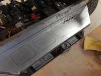
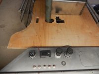
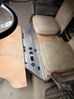
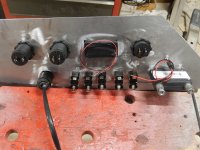
I fired up the propane shop heater and spent some time cutting out the dash and installing the switches.
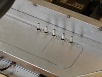
DSCN5273.JPG
DSCN5274.JPG

Mockup where the other components will go

DSCN5276.JPG

How it looks from the drivers perspective
The washer to the right will be the key switch
The theory is that when I switch on the voltmeters I will be able to read the voltages
for the 48-volt battery and the 12 volts coming from the converter. (At the same time) 🤔

DSCN5277.JPG

And here is another "it went where?" story.

The indicator light I ordered was supposed to come from Chino which is about 50-ish miles from me.
Start at the bottom and follow its journey. All I can say is, "You've got to be kidding!"
About seven days to go 50-ish miles. Not bad Mr. DeJoy.

DECEMBER 28 - 12:22 PM Delivered, In/At Mailbox Apple valley, CA
DECEMBER 28 - 6:10 AM Out for Delivery Apple valley, CA
DECEMBER 28 - 4:20 AM Arrived at Post Office Apple valley, CA

DECEMBER 28 - 3:13 AM Arrived at USPS Facility Hesperia, CA

DECEMBER 28 - 2:11 AM Departed USPS Regional Facility San Bernardino CA distribution center
DECEMBER 27 - 8:24 AM Arrived at USPS Regional Facility San Bernardino CA distribution center

DECEMBER 27 - 6:00 AM Departed USPS Regional Facility Los Angeles CA network distribution center
DECEMBER 27 - 2:22 AM Arrived at USPS Regional Facility Los Angeles CA network distribution center

DECEMBER 26 - 12:00 AM In Transit to Next Facility

DECEMBER 25 - 10:45 AM Arrived at USPS Regional Facility Elk Grove Village IL distribution center

DECEMBER 25 - 8:25 AM Departed USPS Regional Facility Chicago IL network distribution center
DECEMBER 24 - 8:57 AM Arrived at USPS Regional Facility Chicago IL network distribution center
DECEMBER 24 - 8:09 AMDeparted USPS Regional Facility Chicago IL logistics center
DECEMBER 24 - 6:29 AM Arrived at USPS Regional Facility Chicago IL logistics center

DECEMBER 22 - 10:57 AM Arrived at USPS Regional Facility San Bernardino CA distribution center

DECEMBER 22 - 9:29 AM Departed USPS Regional Facility City of Industry CA distribution center
DECEMBER 22 - 3:26 AM Arrived at USPS Regional Origin Facility City of Industry CA distribution center

DECEMBER 22 - 2:11 AM Accepted at USPS Origin Facility Chino, CA
DECEMBER 21 - 6:40 PM Shipping Label Created, USPS Awaiting Item Chino, CA
 
Happy New Year to all my ES friends and helpers.

A huge thank you for all the tips and advice this past year.
It has been invaluable to the progress of this build.

Things are looking up for a possible completion by year's end.
This next phase, wiring the 12-volt system, will enable some more road testing leading to the breakdown and final fab work and cosmetics.

But first I wanted to familiarize myself with my own diagram.
I printed out my diagram to get a better grasp of what goes where.
The measure twice cut once logic.

While following the various paths I found I needed/wanted to know what my battery voltage was right from the start.
I also found that I had to turn on the 12V socket to read the 12V voltmeter.
And I still needed a switch for the horn.

Soooooo I rewired it ...again.

Now when I throw the circuit breaker I get a reading of the battery. and the battery's on/off light will come on.
When I turn the key switch the 12V voltmeter will come on and the 12-volt system will energize.

If I have done the rewire correctly I'll have two separate systems
with two separate voltmeters giving me constant simultaneous readings of both systems.

The switch for the 48V voltmeter (previously) is now going to be used for tooting my own horn... :lol: (Light green line)

Updated diagram
fUSE BOX WIRING - ReDo.png
 
That looks good. Some car horns draw a lot of current and may be too much for the dc-dc. You may need to experiment with those. Any "electronic" horns that use a loudspeaker will be much lower current than an old school mechanical horn. Something from a smaller car or motorcycle will be OK.

The only other thing I question is the headlight dimmer. I only see two wires going to the headlights. For high/low beam lights, there will be one ground and a separate terminal for high and low beam, 3 total. If you only need one beam, you can probably skip the relay and wire directly to the switch.
 
fechter said:
That looks good. Some car horns draw a lot of current and may be too much for the dc-dc. You may need to experiment with those. Any "electronic" horns that use a loudspeaker will be much lower current than an old school mechanical horn. Something from a smaller car or motorcycle will be OK.

The only other thing I question is the headlight dimmer. I only see two wires going to the headlights. For high/low beam lights, there will be one ground and a separate terminal for high and low beam, 3 total. If you only need one beam, you can probably skip the relay and wire directly to the switch.

Thanks, fechter

I did forget to include the wire going to 87a.

Not sure yet what the Ooga horn amp draw is. It calls for a 30 amp fuse. https://manuals.harborfreight.com/manuals/96000-96999/96291.pdf

The converter https://www.ebay.com/itm/223130887152?_trkparms=amclksrc%3DITM%26aid%3D1110006%26algo%3DHOMESPLICE.SIM%26ao%3D1%26asc%3D235874%26meid%3Da76e4b2e78504edabdd4a4ec11278d09%26pid%3D101195%26rk%3D2%26rkt%3D12%26sd%3D185208614218%26itm%3D223130887152%26pmt%3D1%26noa%3D0%26pg%3D2047675%26algv%3DSimplAMLv9PairwiseWebMskuAspectsV202110NoVariantSeed%26brand%3DPRO&_trksid=p2047675.c101195.m1851&amdata=cksum%3A223130887152a76e4b2e78504edabdd4a4ec11278d09%7Cenc%3AAQAGAAACEAgKyWhZIxZeObnvkFtBFUq0YhZtFs9EUuL0Eb4g3UBaQ5ALV%252BRaKrrNNsejlL7fmLyRb95mxjC%252Fx07Ty2Lr5xiezArWpJYiuWDwr%252Fx4LzcQZ9z1LlOSunwXwIq0Vwg0uK451BLwC7QtdM0q6W%252B%252FSKXBqZ6rzGK7KzGzGNH3dXKrzYa2GdQH7NmZmFoAE12HWZSWzw9GiIpLVRzO94HwyMpZ3%252F5GGq1iCNV3I8SB23WwtAit64iPr17DAnAPOJRYp%252FL%252F2MeNl1mGYawfXZAIDP4edqDNEpn%252FRu5EyDY3G8%252Bri4aWDmeoHsWjQJ9UznpQ7scqF7K0DpOVutTSXGTj%252FGY0wWxvbxrtdwzh%252Fr58cAaKjkmJ%252BRQng0xdxNXpOeklb1AUqhJ4xenjHepcpGLuLcYt9gkYD4tlaVsq2PPRLj%252B8Jw18JDvAFCDrDTg05lO%252FNChZP3DAHaYUnUJpLcEHQXUq9tPS73JcVK7rcEMljSVu%252B7bKf3rJYpzYMjckoyqndwfnkYprxFrsRyWHdrXZTSlIhAHeY9N3OxxkUql3o7H2YPC8yqGRm5jW8Vh54my0gNvh5dC8hyHmcPfFkLSUnEKHYvFvfWEla8jqz1%252BOIjPGKdtp8%252Fu4UiNUfgG3zDyKor0N%252B4gz7NJBmpy9WeSXQB5RyOsJiTG3%252BCTkOcq5bG6ifMLRsiZjxcX%252B2HpZYVp2AQ%253D%253D%7Campid%3APL_CLK%7Cclp%3A2047675 output is 20 amp max. Will that have any bearing on its use for my application?

Also, the lights and the horn use 30 amp fuses. should I reduce their size down to 20 amp?

Actually, the question should be;
'because the dc-dc is 20 amp max, there should be no fuse larger than 20 amps????'
 
MEGA RATS !!!

Anyone, see a 'GO' switch. You know, like go forward or go backward?
Me neither :x

I have the switch. It's even wired up. But somehow I missed including it in the wiring diagram.
That itself is not a problem. The problem is where to put it. The design of the dash didn't include it.

Big-time bummer!
 
The dc-dc should have overload protection so the fuses should never blow if they are over 20A. Fuses really aren't even necessary on the 12v side. If you want the fuses to be functional, then they would need to be under 20A. If you find you don't have enough capacity on the 12v side, you could add a second dc-dc or just get a larger one. I think you'll be OK with 20A fuses.

If you don't want to start over on the dash, one option would be to re-purpose an existing switch and have something always on (like the USB socket). Another option is to make a small flat plate switch panel that goes over the existing dash that you can make new holes in. The plate will cover up any holes that are moved.

Another option would be some kind of shifter lever. They make side-mounted ones for motor boats. Too expensive, but you could copy the general design and make your own. You'd want some kind of safety to prevent shifting it accidentally while in motion.

boat shifter.jpg
 
Thanks, fechter

My ignorance of electronics is obvious more often than not. If I really don't need any fuses, on the 12-volt side,
then I suppose I'm wasting time and money.

I was looking at the option of using the USB port toggle position. Replacing it with a DPDT On-Off-On switch.
And as you say make the USB always-on or on-off with the 12-volt socket. I did look for switches with a safety cap. The existing switch is large and easily switched if bumped. Not good if I'm doing full speed down the road, I thinking... :shock:

Also thinking about making an enclosure to mount the existing switch up on the steering column.

Not too late to change things. Need to get the end product right.
The USB and 12-volt socket were part of the original 5-gang switch panel.
They just migrated over to the new panel, for no real reason.
I may find another out-of-the-way place to mount them.
They will be used very little but will be handy when the time comes.

There are only two requirements that would require power outlets. Sound equipment and or accessory lighting.
 
If you use 20A max fuses, they may still be useful. It's better to lose only one branch instead of everything if you get a short. Also good for troubleshooting. The 12v socket and USB are definitely useful. Lots of accessories use those.

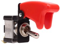
They make switch safety covers you have to flip up to access the switch.

switch cover.jpg

These are common on aircraft. You can find these pretty cheap. Just an idea.

The ideal thing is some circuit that prevents switching unless the speed is zero. But that is pretty complex and not going to be worth it. This should actually be in the firmware for the controller, but most cheap ones won't have this feature. You can test by running the motors slowly with the wheels up or the chain off, then switch and see what happens. If it switches when it's going too fast, bad things will happen.
 
I broke an axle on an MXUS like that once, testing the SFOC5 and I am pretty sure it somehow lost position sensing and reversed rotation instantly at the same torque level it had been driving me forward. :(


one example of switch cover
https://www.amazon.com/Antrader-Plastic-Toggle-Dustproof-Waterproof/dp/B07L2S38JT
no idea of that item's quality, etc

I still have a few actual aircraft ones (off a decades-old 737 engineer's station panel, from the fuel pump switches I think). Kinda dingy looking but yours for cost of shipping if I can find them. Might still have the gauges too; not sure; no idea how to drive them.
 
Today was truly electrifying

The first thing I did was get rid of the 70 amp breaker.
Last night I came up with a solution where I will be able to get to the battery breaker when needed.
We'll let that come as a surprise later on.
I was able to get everything wired as diagramed and nothing sparked or blew up.
Voltages check out for both @ 12.1V and 55.5V.

At the moment the only thing that seems to be controlled by the key switch wiring is the go-no-go part.
Had to toss the key switch that came with the motor kit. It's cheap and has come apart. I'll be looking for a better one.
Probably a 'barrel' key type. Right now I'm using a temporary on/off switch I have, from who knows where. But it is working.

I have done a (wheels up) run, check of the drive system, and all works as designed/desired.
Next, I believe is to run the wires for the remaining 12-volt accessories.

Starting with the wires to the toggle switches.

So it's been a good day. A productive day. A satisfying day... :D

 
nicobie said:
That looks nice, shame to mess it up with all those silly wires. :mrgreen:

I wonder if it's possible for you to get some kind of a street legal license for it?

Here in Calif there is such a thing as a NEV _ Neighborhood Electric Vehicle. I have, from the beginning, been building this with those requirements in mind. I have to the best of my DMV research and knowledge built this to meet the state NEV requirements.

Will I register it when the time comes? Not sure at this time. The first goal is to get it parade-worthy and be able to show it around at some of the local, car shows that are frequent around this area.

About those silly wires. I would look 'silly' on the parade route with a car that had to be pushed, now wouldn't I? :lol:
Or maybe I could use the motoring technique the Flintstones used. :p
 
Back
Top