Lyen controller issue

Joined
Feb 19, 2010
Messages
369
Location
Antioch, CA
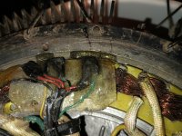
Hi, I recently bought 2 9 get controllers from Lyen for my dual motor scooter build. I made a Y harness for the throttle that had the polarity of the throttle wires correct but didn't use it because I was hooking up one controller at a time, needless to say I hooked the throttle up with the polarity reversed and burned out the throttle. Also while I was hooking up the hall sensor wires the pins kept touching each other and maybe burned something out.

SYMPTOMS: The wheel doesn't spin when the throttle is plugged in (I know the throttle is bunt out, but if I plug it into the other controller after powering it ON the wheel goes full speed)

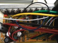
When I check the voltage across the + and - of the hall sensor plug the voltage is 2.8v. The voltage of the blue, yellow, and green wires is 3.5v with respect to ground.

I'm not too sure what happened. I do know the other controller works fine with both motors. I emailed Lyen but haven't heard back, maybe he's on vacation for the holidays. I thought I'd post the problem here and see if anyone knows what the issue is, perhaps it's something I can fix. Any help would be much appreciated.
 
When it is not hooked up to anything, otehr than power (no motor, no throttle, etc), is it also that low voltage? if so, probably the 5v supply is damaged.

You can compare it to the working controller to determine what part is actuallly failed, but if it has 3-pin part labelled 7805 then that's probably it. Probably near the MCU towards a board edge.
 
Yes, I just hooked the power leads up now and the voltage across the + and - and still under 3v, and the three hall sensors have a voltage of 3v. I pulled the controller apart and didn't see a 7805 voltage regulator. I was trying to trace where the wires go, but haven't found anything. I took a few pics, hopefully they're clear enough to see what I'm talking about. Thanks for the reply amberwolf.
 

Attachments

  • image1.JPG
    image1.JPG
    66.3 KB · Views: 656
  • image3.JPG
    image3.JPG
    61.7 KB · Views: 656
shortcircuit911 said:
Yes, I just hooked the power leads up now and the voltage across the + and - and still under 3v, and the three hall sensors have a voltage of 3v.
Do you mean the sensor wires, coming from the controller, with no motor hooked up? Nothing but controller and battery?

If so, then the 5V from the controller is damaged.

If not, unhook the motor and recheck. If the 5v comes back, a hall sensor is probably damaged and is dragging the 5v line down. If it doesn't, it's the 5v in the controller.


I pulled the controller apart and didn't see a 7805 voltage regulator. I was trying to trace where the wires go, but haven't found anything.
Use your meter to measure voltages, and wherever you see the same 3v it's probably supposed to be 5v.

It looks like you have the newer style low-voltage supply, (LVPS), which is a switching type. I don't know enough about that particular one, but there might be a troulbeshooting thread for one somewhere. I tried to find it in a search but didnt' see it if there is.

The lower left corner of the board is the area that supply covers; you can probably see on the bottom where all the traces are concentrated for it, probably looks "separate" from the rest, mostly.
 
So i looked in the lower left corner like you suggested and found a 5v regulator. I checked the output and its 5.1v, however the input was 3.67v (I'm assuming if you're looking at the flat side of the of the chip is the front. So if you're looking at the flat side of the chip; the left and center pin (input im assuming) is 3.6V, and the right leg and center pin are 5.1v. I also checked the voltage of the two outside pins and its 1.5v, not sure there should be voltage there. I sent Lyen another PM but still haven't heard from him. Any thoughts?
 

Attachments

  • image1.JPG
    image1.JPG
    57.5 KB · Views: 605
shortcircuit911 said:
So i looked in the lower left corner like you suggested and found a 5v regulator. I checked the output and its 5.1v, however the input was 3.67v (I'm assuming if you're looking at the flat side of the of the chip is the front. So if you're looking at the flat side of the chip; the left and center pin (input im assuming) is 3.6V, and the right leg and center pin are 5.1v. I also checked the voltage of the two outside pins and its 1.5v, not sure there should be voltage there.
I don't recall what order the pins are in for that package, but you could go to the manufacturer site to be certain. I don't know who that specific one is, but any TO-92 case style 78L05 pinout is probably the same as yours.
https://en.wikipedia.org/wiki/78xx (datasheet links at bottom)

However, it's just as easy to trace the conductor from any of the +5v-marked pads on the board, like the red wire on the halls, throttle, ebrake, or programming connectors, back to whichever lead on the 7805 chip. I'ts probably the righthand lead in that pic, but check to be sure.

Then the ground lead is probably the center lead; again you can trace that to any ground pad (black battery lead, black wire for hall, trhottle, ebrake, programming, etc).

Then the input is the remaining lead, probably the one on the left, and that is usually 12V or so input to it.

The voltages you're getting can't be correct, because it can't produce 5v out if it doesn't have *more* than 5V input, for that type of regulator. ;)

My guess is the 5.1v you're reading is actually on the input, because the output voltage will be the same as whatever you get on hall/throttle/ebrake/programming +V (usually red) wires. Since that was about 2.8v under load in the first post, it would make some sense (with voltage drops and whatnot) for a bit more than 3v on the output (though it should be 5V, indicating something isn't working right).

If the input voltage is only about 5V or less, the regulator might be working, but unable to supply the 5v because it isn't getting enough power itself.

That means whatever supplies the 12V isnt' working right, either damaged or something else is loading it down (as it also usually supplies the gate drive voltages for the phase FETs, if one of those is damaged or the gate drivers are, it could drag down the 12v and cause the problem).


At this point, since no schematics are readily available for these things, and even the incomplete ones around ES are probably for versions different from yours, your best way to fix it outside of Lyen doing so for you is to compare readings from one controller to the other, since you have one working and one not--but you should be careful so you don't break the working one. ;)
 
Ya after reflecting back on my basic electronics knowledge (been out of school a few years) a voltage regulator only drops voltage down. I couldn't find the data sheet on that specific part, the others had a similar number but one was an SMT chip and the other looked like a MOSFET. There was a 15v SMT regulator in the board, but it can be really risky trying to check the voltage of that thing. I think I'm just going to wait for lyen to get back to me. I'm not setup at home to be working on electronics boards. I was hoping it was an easy fix like replacing a through hole 7805 regulator. I'll keep you posted, I really appreciate the help amberwolf!
 
One of the hall sensor went out on the motor and I'm not sure but the phase wires add some insulation missing and they could have touched. But it stopped working and I had to walk it out and I found a bad hall sensor in the motor I have since replaced the hall sensor in the edge 1500 motor 35 mm. It works fine up in the air if I rotate the wheel first.
 
So I disconnected the 12fet. llyen controller and and Dug out the 9fet Lyen controller hooked it up it worked great except for there was a clunk clunk in the wheel.
I cut three holes in the side plates long time ago about an inch and a quarter. I looked inside as it was spinning and I saw a little sparking I pulled apart the motor and put some JB weld on it and then ground away the fins on the inner side of the cover on the wire side same side as for the Halls are connected I actually saw Sparks coming out of the holes so I knew something was up.
 

Attachments

  • IMG_20230526_192406615.jpg
    IMG_20230526_192406615.jpg
    4.6 MB · Views: 0
  • IMG_20230526_192353340.jpg
    IMG_20230526_192353340.jpg
    2.7 MB · Views: 0
  • IMG_20230526_190223487.jpg
    IMG_20230526_190223487.jpg
    2.3 MB · Views: 0
Last edited:
This is Lyen's 9 fet 30 amp controller at 72 volts and rshunt at 2.00 and the C.A. shows 2.25amps and it flys . Like it's going to take off I might have a false positive I guess I won't know till I put it on the ground and put a load on it. ?
 
Wow I put the smaller 9 fet controller on the edge 1,500 motor with 2in. Holes in the side covers and saw Sparks from the hall sensors area inside. So put the edge 1,500 aside. And pulled out the volmart 1,500 watt motor but looks like a 28mm ?
So the 9 fet and volimart works fine on stand. Then tried the 12 fet Lyen controller and wouldn't start. I rotated the wheel and when spinning turn the throttle and it worked..
So did I blown the 5volt circuit and how can I fix it ? What controls the five volt circuit and can it be repaired by me ? Or can I just run this controller with a peddle start and not totally blow the controller ?
 
Back
Top