Motobecane 50V Conversion

RoseArk said:
Oh I like the clamping torque arms! What are / where do I find those brackets that the clamp bolts run through? I don’t know that I have seen something like that before.
They are used to clamp steel cables (like dog tie outs, pole guy wires, etc) together after looping them around something. Sometimes they are called "wire rope clamps"; this is a randomly found amazon link for the type of thing:
https://www.amazon.com/Cable-Clamps-U-Bolts-Galvanized-Clips/dp/B07CRW455Y
5191AL+IMDL._AC_[1].jpg

You'll use only four of the cast parts, and maybe the nuts/washers, not the u-bolt. You'll get a piece of threaded rod and cut four pieces out of it of the length desired if you want to use the existing nuts/washers, or better is to get some good bolts, nuts, flatwashers, and lockwashers (four complete sets).


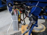
If your plates are steel, you can also weld a bolt-stop (steel cylinder just big enough for the bolt's diameter) and a thread-receptacle (stack of nuts, etc) to the end of the plate like this:
https://endless-sphere.com/forums/viewtopic.php?p=1737530#p1737530
file.php


But the cable clamps work, and require no modifications to use.

I used the welded-on solution because my dropouts are vertical, and I didn't want to risk ever having an issue of loosening hardware causing the clamps to fall off somewhere during a ride (unlikely, but if it can go wrong, it'll probably happen to me, so I try to pick a solution that fails in a way I can recover from :lol: ).
 
CONSIDERABLE SHOUTING said:
Nice conversion! Are you gonna keep the standard battery pack hanging off the front, or are you gonna replace it for something bigger/different?

Also, good to know a 500 watt hub is similar in top speed to a 50cc two-stroke. It's always hard to explain equivalent eBike power well to people.

I was honestly surprised and considered just getting a bigger controller and battery to run the motor I already had. I do want a bigger battery for the front as what is there just isn’t enough. I think it maxes out at 22 or 25 amps. I am thinking about a jumbo shark at 52/60/72 volts but not set on that yet as there is space for something bigger. The shark style is nice as it mounts really easily and kind of maintains the “look” of the bike. Regardless of what I go with…looking for something with minimum 40 amp output but would like 50 amp if possible.
 
Yes, those U-bolt saddles are exactly them. Any major hardware store has them. I seem to remember them in the steel wire rope aisle. They would cut cable to length, then you could fold over the end, and clamp them with these to make a loop.

https://www.youtube.com/watch?v=HKt6kswEAXo

The "bolts" are called all-thread rod with a nut at each end. Put the nut on before cutting the rod to length, then de-burr the cut, then when you remove the nut, it will straighten any irregularities on the threads.
 
Well I got back from holiday travels this week and started back into this project. I had shorted a ground wire on the display harness from the controller. I got that fixed but as I suspected, when I shorted the display wire I also, I believe, fried a hall sensor. Testing the hall sensors, my blue sensor is not working. Testing at the harness, the blue sensor was registering a few mv on the volt meter. The others as well as red to black read 3.7 and -0.4. Not the 0 and 5 I was expecting but I am going to assume that’s what they should read.

14E6A4BC-EB2E-4E7B-A4AD-7CCB4C78975E.jpeg

I disassembled the motor today and it looks like I have lots of material to remove to get access to the board and sensor for repair. Any suggestions on removing the material and what to use to reglue the board back in place after I replace the hall sensor?

Thanks
 
RoseArk said:
I had shorted a ground wire on the display harness from the controller. I got that fixed but as I suspected, when I shorted the display wire I also, I believe, fried a hall sensor. Testing the hall sensors, my blue sensor is not working. Testing at the harness, the blue sensor was registering a few mv on the volt meter. The others as well as red to black read 3.7 and -0.4. Not the 0 and 5 I was expecting but I am going to assume that’s what they should read.


If you are not testing with the controller and motor connected, and powered on, you won't get valid hall signals. The hall sensors only ground the connection when active, they do not output any voltage. The controller hall signal lines have pullup resistors on them to (usually) 5v, so if you get no voltage on the hall signals with motor and controller connected and powered on, then the controller itself has a fault that is not putting voltage on the signal lines, and that usually means the 5v inside it (or the entire LVPS) is dead.

That can (but does not always) mean the MCU itself is dead, since it's often powered from that 5v and anything that takes out the 5v can take out the MCU too, and anything that is powered by the 5v, which includes hall sensors, throttle, PAS sensor, etc. If the MCU is dead, the controller will typically do literally nothing, including talking to the display or responding to display commands, etc.

Note that shorting the ground wire (there is only one) on the display/controller connector shouldn't damage anything on the halls, etc. Shorting the battery wire on the display to a communication wire, of which there are two, could damage the MCU (display and controller) in a way that drags the controller 5v down to prevent halls from getting any pullup on the signal lines (or any power on the supply line).

Shorting the ground wire to the battery wire could blow the battery BMS, or fuse, but then you just wouldn't have any power.

Shorting the ground wire to comm lines might damage the comm line and prevent display/controller communication, but doesn't take anything else out normally (and wouldnt' affect the halls).

Shorting the ground wire to keyswitch wire is the same as the battery wire if it was on, and would usualy damage just the display's ability to turn the controller on at all. (so the display would turn on, but the controller won't, because it gets no power from the display to run it's LVPS).

There aren't any other wires in display/controller connector in most systems.
 
amberwolf said:
If you are not testing with the controller and motor connected, and powered on, you won't get valid hall signals. The hall sensors only ground the connection when active, they do not output any voltage. The controller hall signal lines have pullup resistors on them to (usually) 5v, so if you get no voltage on the hall signals with motor and controller connected and powered on, then the controller itself has a fault that is not putting voltage on the signal lines, and that usually means the 5v inside it (or the entire LVPS) is dead.

I tested with everything connected and turned on. Prior to Christmas vacation I was riding around with no display and the PAS, throttle, and brake signals all worked. However, I would regularly get hall sensor errors at startup as determined by connecting to the controller with my phone. I fixed the display wires yesterday and powered it up with the display and then tested voltages for the hall sensors at the harness.

amberwolf said:
Shorting the ground wire to comm lines might damage the comm line and prevent display/controller communication, but doesn't take anything else out normally (and wouldnt' affect the halls).

It is possible I shorted something else while I was moving things around and the two problems just happened on the same day but at different instances. I really don't think it is a controller problem but for a couple of dollars I can track down a hall sensor and rig up a harness to connect this controller to my spare motor and my spare controller to this motor and see what happens.
 
RoseArk said:
I disassembled the motor today and it looks like I have lots of material to remove to get access to the board and sensor for repair. Any suggestions on removing the material and what to use to reglue the board back in place after I replace the hall sensor?

Thanks

If I were doing it, I'd identify the bad sensor, clip the legs so there enough left exposed coming from the board to splice/solder to the new sensor to, yank the bad sensor and replace, solder the legs, and either use some hot glue or silicone to pot them in place. That way you don't have to mess with the board and all of that messy stuff.
 
Thanks Amberwolf for precise knowledge overflowing and also E HP for the FETlegs trick!
 
I made a little progress over the past few weeks. First, I replaced the hall sensors and board in the motor. It ended up being easier to replace the board and sensors as a whole rather than just a single hall sensor. I tested the motor with one of those cheap motor/controller testers and connected the motor to one of my small controllers and everything seemed to be working. I then tested the controller with the cheap tester and none of the hall and phase wires were working according to the tester. Bummer.

I opted to upgrade the rear swingarm to the mbk 51 for Motobecane mopeds. It has a 150mm drop out which gave me a lot more room to comfortably fit the disc brake, is much more stout than the factory swingarm, and is making it a lot easier to add further supports. The downside, it has 12mm flats and will require a shim welded in.

C2B52B71-010B-44D3-9A4F-8F893D8EFC99.jpeg

I made progress getting the rear brake hooked up. Progress after this picture and actually functioning though I still need to bleed the brakes yet.

704F83D6-3737-4CCF-95E3-1B6FE4604F3D.jpeg

Current to do list. Track down some metric bolts to finish installing the shocks. Wrap up the first drafts of the swingarm support brackets. Deal with controller. And the chain is a smidge too long to work on the middle gear…so fix that.
 
Positive progress! Had to get a new controller and opted to swap battery and controller locations. Moving the controller up front made it a lot easier to clean up wires and I will be able to hide the battery wire eventually. Still some cleanup to do. The little battery on the back is giving me roughly 15 to 18 amps and rolling me along at about 25 mph or a tad more on flat ground.
53A70F80-B53A-4B45-B78B-5EEBB2DFAD68.jpeg

F4FDBD81-BA29-426A-B2C9-9EDDE28ED435.jpeg

6863918A-56DB-4E9F-8B40-E21C1661A1DA.jpeg

Next up, finish touching up a few things, headlights, taillights, tighten chain, and new battery. Not sure what I am going to do for a battery yet. Went for a little ride today and thoroughly enjoyed the trip through the neighborhood. It’s so quiet and smooth.
 
Positive progress! Had to get a new controller and opted to swap battery and controller locations. Moving the controller up front made it a lot easier to clean up wires and I will be able to hide the battery wire eventually. Still some cleanup to do. The little battery on the back is giving me roughly 15 to 18 amps and rolling me along at about 25 mph or a tad more on flat ground.
View attachment 330440

View attachment 330442

View attachment 330441

Next up, finish touching up a few things, headlights, taillights, tighten chain, and new battery. Not sure what I am going to do for a battery yet. Went for a little ride today and thoroughly enjoyed the trip through the neighborhood. It’s so quiet and smooth.

Yesterday I got the rear brake wired in and spent some time putting loctite on many of the bolts. Tonight I went for a little ride and made it up some pretty steep hills. It took about 950w to make it up the hills at about 20mph. I am definitely at the limit of my 48v battery but pleased. I ordered a battery upgrade…72v and 20ah. I really struggled with mounting it on the back rack or on the motor mount. There is room to mount it in front of the controller and it would be nice to keep weight balanced but ended up going going with a rack mount option. I have a future project planned and wanted to be able to easily move the battery back and forth.

I think this is what I am going to use to power my 12v (I think the bulb is 12w + tbd on taillight) headlight.
Dc-dc converter

It’s nice to be chipping away at to-do items again.
 
Working on the rats nest. I removed a bracket from the frame that was no longer needed to free up some space around the wires. Currently I am working on the dc-dc converter for the headlight, horn, and taillight. I think I should do something different with the power and phase wires. There is a lot of extra wire there and it gets kind of close to the chain. Not sure what at this point…time to do a little searching and see what others are using.

I did get a small 72v 20ah battery. Looks like I should reach speeds of about 40mph which is plenty for my needs. I haven’t tried the new battery on the hills yet so not sure what those speeds will be.

I also think I am going to install an antispark switch because my dc-dc converter is directly tied to the battery. It would be nice to have a complete kill switch since I don’t ride the bike every day. I think this: Antispark switch.
 

Attachments

  • 5A1379C9-BA9B-4B97-8E9B-D79A4790F073.jpeg
    5A1379C9-BA9B-4B97-8E9B-D79A4790F073.jpeg
    2.6 MB · Views: 3
Your BMS does the same job that switch will do. ;) If your BMS has a place for an on/off switch, then use that to turn the system on and off for the same effect without the extra hardware cost, space used up, wasted energy during use, and potential failure point.

If it doesn't have a place for a switch, but has a place for a thermal cutoff, you can install a switch in series with the cutoff (or parallel with it, depending on the type of thermal switch it uses).


If you require an independent switch, a less complicated and therefore more reliable precharge / antispark switch is to use a large resistor and a 3-position switch (off, precharge, on). It's bulkier, though it wastes less power. (however, it needs to be placed directly on the battery output wiring, unlike the BMS or antispark module switch that can be placed remotely nearly anywhere you want. )
Thanks Amberwolf! I always appreciate the support. Do they make 3 position switches that will handle 72v? The Blue Sea Systems and (I forget the other brand) were only listed at 48v. Suggestions or suggestions on search terms to use? Thanks.
 
Since you are tidying up the wiring you may want to consider inverting the orientation of the controller. The wiring grommets are not waterproof, and near impossible if not impossible to waterproof (even by slathering them in silicone caulk). Having them facing up as yours are makes them a waiting target for moisture intrusion, especially if you get caught in a rain during your daily rides, or even running thru a puddle.
 
Since you are tidying up the wiring you may want to consider inverting the orientation of the controller. The wiring grommets are not waterproof, and near impossible if not impossible to waterproof (even by slathering them in silicone caulk). Having them facing up as yours are makes them a waiting target for moisture intrusion, especially if you get caught in a rain during your daily rides, or even running thru a puddle.
Thanks! Someone had previously mentioned doing that with my motor wires…good idea to do on the controller as well. Much appreciated.
 
Thanks Amberwolf! I always appreciate the support. Do they make 3 position switches that will handle 72v? The Blue Sea Systems and (I forget the other brand) were only listed at 48v. Suggestions or suggestions on search terms to use? Thanks.
Unless you need to disconnect it under load, then it shouldn't make too much difference about the voltage---just the current on the "on" position of the switch (has to be able to handle the full controller load), because if you precharge then the resistor will limit current across the precharge contacts during connection, so any arcing will be very limited (if you have a correctly sized resistor). When you turn the system off, the potential is the same on both sides so no arcing (unless it's under load), no current flow.
 
I can’t believe how fast time is going this spring. Slow progress but working on lighting. I found a 4.5 inch led light that fits the original headlight assembly. I was hoping to use the original horn but it appears to no longer be working. I even found a nice horn button.

Main power is coming from he dc-dc converter up to the headlight. From there power is fed to the original headlight switch, to the horn, and back to the taillight. Took me awhile to get the switch right…had things backwards when I reassembled the switch after cleaning. I am debating on tapping the brake lights up by the handle bars to minimize number of lines running underneath to the controller.

Pictures are from testing as I was waiting on some crimps and heat shrink.

I also made a few changes to the bracket holding the controller and converter but apparently forgot take pictures a few weeks ago.58ADDFDD-394F-4D24-8112-75FC825EC91D.jpegB43D6343-EDC5-4761-BE44-AD6A92327BDA.jpeg7B7D9048-A1D5-4FFF-BC33-F40FE3067AE9.jpeg
 
Back
Top