"User Friendly" Motor Physics

safe

1 GW
Joined
Dec 22, 2006
Messages
5,681
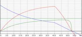
The formulas for an electric motor are very straight forward. In order to plot the performance of an electric motor you need to know certain constants such as the "No Load" amps and speed, the electrical constants for voltage and resistence of the motor and the maximum voltage you plan to use. I'm going to wait and see if anyone wants to get into the actual formulas on a spreadsheet before getting into them. Instead I want to go at this from a "high level" of just looking at the charts that these motors produce.

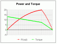
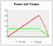
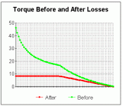
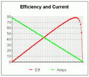
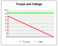
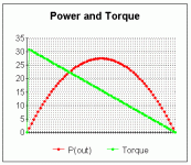
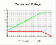
The first set of charts will be for an "Uncontrolled Motor" which means that it has no controller limiting the voltage. In real life you won't likely be experiencing such a motor because it's not very efficient over the full powerband. So let's look first at these charts:


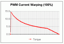
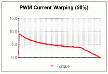
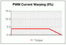
Note: All charts read from 0 rpms on the left to max rpms on the right and the values have been adjusted to fit the charts, so don't obsess on exact numbers as a lookup, they are often scaled to fit... but the shapes are all correct, which is the important part.
 

Attachments

  • uncontrolled - efficiency and current.gif
    uncontrolled - efficiency and current.gif
    5.6 KB · Views: 5,831
  • uncontrolled - torque and voltage.gif
    uncontrolled - torque and voltage.gif
    4.9 KB · Views: 5,829
  • uncontrolled - power and torque.gif
    uncontrolled - power and torque.gif
    5.2 KB · Views: 5,829
Okay now let's add a controller to this motor (which happens to be a generic 36 Volt 750 Watt Unite motor) and have this controller set the current limit to 40 amps. Now those same charts look like this:
 

Attachments

  • 40 amp - torque and voltage.gif
    40 amp - torque and voltage.gif
    4.9 KB · Views: 5,821
  • 40 amp - power and torque.gif
    40 amp - power and torque.gif
    4.9 KB · Views: 5,821
Okay, now there are a million ways to go with this, but the purpose of me getting into this is as a response to the thread about a "Hub Motor" that was producing some rather bizarre simulation results. I'm "intrigued" by what that simulation produces and it IS POSSIBLE for an electric motor to behave in that manner, but it would not be using a controller that sets a "standard" current limit which is a fixed amount. Hopefully this "from the ground up" review of the basic physics of electric motors will shed light on this paradox... :)
 
:idea: Philosophical Thought About Electric Motors

The "central idea" to concentrate on in dealing with the powerband of an electric motor is that EVERYTHING about the shapes of the various curves that a motor produces comes into existence because of the:

Voltage - Rpm relationship.

:arrow: An electric motor is entirely controlled by it's voltage at a particular rpm...
 
:arrow: I'm pretty sure I've figured the Simulation out. Check out this chart, it accurately reflects what the Simulation chart looked like. What they seem to be doing on the "Hub Motor" is the controller limits the current to 35 Amps at it's "peak power" area and then appears to allow the current limit to rise much higher as you get into the lower rpms. This chart reflects the "bulge" very well. All I did was "forced" the voltage to a linear drop from the "peak power" area down to (in this case) 15 Volts at near zero rpms. Normally at near zero rpms you would be at 9 Volts for this particular motor.

So either the Simulation was created incorrectly (being overly generous in overstating the low rpm torque) OR they have a really cool controller that is allowing double the current at low rpms.
 

Attachments

  • Simulation - power and torque.gif
    Simulation - power and torque.gif
    5 KB · Views: 5,804
Another possible explanation is that a Brushless Motor works on an entirely different set of physical principles than a Brushed Motor. It's possible that there might be effects that don't exist in one type that do exist in another. The only "concrete" statement that can be made is that the Simulation for the "Hub Motor" does not reflect the "standard" motor - controller physics that we see on the "regular" brushed motors. Even the Etek and PMG132 Motors don't exhibit these types of physical properties, but they too are brushed to my knowledge.
 
safe said:
So either the Simulation was created incorrectly (being overly generous in overstating the low rpm torque) OR they have a really cool controller that is allowing double the current at low rpms.

My bets are on the first reason. I don't know of any controllers for e-bikes that double the current at low rpm. If they did, seems most motors would turn into a toaster so limiting the current at low rpm seems a lot safer than at high rpm (assuming you'll be going faster, thus the air cooling motor/controller/etc) I could be wrong, someone may post up a link to such a controller, but I think your suspicion of the "AI controller tested" theory might be the cause of the variance in their charts.
 
My guess is that the Simulation was improperly put together and the error was probably not intentional. But what happens is that "good results" tend to be easier to "accept" if you are a believer in your product. So it's one of those things where an error got missed because it "felt good" to let it exist that way.

But we might be wrong, they might have some really "trick" technology that is tweeking things in ways we do not yet understand.

Doubtful, but possible...

We KNOW that it's POSSIBLE for even a regular "brushed" motor to behave like that, but how would the controller know what rpm it was at so as to "boost" the low end torque by allowing higher current? You would need a controller that "knew" what the rpms were and could adjust the current limit appropriately. Maybe they have some sort of built in Hall Effects Sensor to measure the rpms? I don't know...

It's important to realize also that it wasn't just a case of the current limit being too high, there was an actual "variable current limit" going on. It's the only way to get a power curve with that "bulge" in it. The "bulge" is the effect of the current limit being progressively raised as you get into lower rpms.

I still hold out the possibility that there is some alternative physics at play because that "Brushless Motor" might have some different charactoristics than the regular brushed ones.


:arrow: If the Hub Motor Simulation is real then I WANT one of those Hub Motors!

(but if it's not then I also want to know)

The way to test this is to measure the voltage at a known rpm under a high load at low rpms. Basically we need a dyno test...
 
The graph above looks like what I would expect for typical controller. The physics of a brushed and brushless motor are the same, so the graphs should look similar (assuming the controller is included in the system).

Torque is directly porportional to motor current. Motor current equals battery current when you are at full throttle and there is no limiting. Once the load increases to the point where limiting occurs, the battery current stays constant, but the motor current increases linearly, just like the graph shows.

You could read another description of how this works here:
http://www.4qdtec.com/pwm-01.html
 
fechter said:
Torque is directly porportional to motor current.

You've stated it correctly.

All the charts I've posted are of the actual physics going on to the best of my knowledge. It took a while for me to master all the formulas, but I've done my homework and I think I know what is going on now.

The bottom line is that the Simulation showed a torque curve that was INCREASING as the rpms approached zero. In a "fixed" current controller the torque should be "fixed" in the same manner. So the Simulation is in error. There should never be a "bulge" in the power curve from the peak power point to zero if you have a fixed current controller.

Never...

A fixed current controller should always have some variation of this power and torque curve:


Note: Observe that the torque is "fixed" to a level equal to the "fixed" current limit. If this were to increase or decrease then a corresponding increase or decrease of current would be expected. The statement "Torque is directly porportional to motor current" is a literal truth. You just can't make torque appear out of "nothingness". It takes energy to produce torque.
 

Attachments

  • 40 amp - power and torque.gif
    40 amp - power and torque.gif
    4.9 KB · Views: 5,765
What is Torque?

For my calculations I've been doing this. I take the Power Output of the electric motor and I divide it by the rpms and then throw in a constant that compensates for "radians per second" as opposed to "revolutions per minute" and that gives me the formula:

Torque = P(Out) / ( RPM * 0.10472 )

Any debate on this formula?

What's nice about doing it this way and not from the current directly is that it also serves as a "check" on the rest of your work. If the result of this calculation is a flat straight line then you are okay. If not, then you know something else in your work is messed up. It's a sort of "safety check" that things turned out right.

It's possible to arrive at torque from other directions as well...
 
Let's take another look at that Simulation chart.

It still appears that there are slight differences between my attempt to recreate it and what is showing, The torque line from the right begins as a straight line and then when you hit the "power peak" it turns into an inverted parabolic shape. Hmmmmmm.....

That would mean that the voltage must be calculated based on something other than a linear drop as in my attempt to recreate it. I simply have no idea what principle they are acting on in order to get that. If it's a "mistake" then it's a very complicated "mistake" to make. That raises a "red flag" because people don't normally create errors that increase the complexity like that. It has me "stumped". :oops:
 

Attachments

  • Simulation.gif
    Simulation.gif
    11.4 KB · Views: 5,724
One observation...

I notice that the curves of power and torque seem to roughly stand as "inverses" of each other. One speculation might be that somehow the torque value was somehow mingled into the inverse of the power value. (with the efficiency curve causing the difference?)

Hmmmmm...
 

Attachments

  • Simulation Curves Crossing.gif
    Simulation Curves Crossing.gif
    14.6 KB · Views: 5,722
Seems that they actually post a disclaimer for their Simulation program:

"Our dynamo setup is presently limited to a maximum loading of about 5 N-m, so it can only confirm the simulation at the higher end of the speed range. When the motor is heavily loaded, it causes all of the copper wires and windings to heat up, increasing their resistance and resulting in less torque and power than the simulator may indicate. There is also a fair bit of deviation from one hub motor to the next from Crystalyte because they are all hand made. This is especially true of the cogging torque, which has an effect on the peak efficiency of the setup. The performance charactersistics listed on the crystalyte website for the 400 series motors seem to be off by about 20%. These values appear to have been generated with an earlier and weaker magnet arrangement."

dynamo.jpg


So it's possible that they really just drew up some charts that weren't really connected to anything of a "formula based nature" and just placed them on the site for rough "ball park" estimates about performance.
 
OK, I see your point now. I would expect a fairly linear torque graph on the left side. Perhaps there's a non-linear loss (like motor windage) that's causing the parabolic shape.

Power = torque x rpm, so it makes sense that the torque and power curves are inverse of each other.
 
Safe the reason for the torque not being a flat line on your previous graph is that the controller is limiting the battery current, but as the rpms drop the duty cycle (voltage out) is dropping also this has the effect of a fixed current going into the controller but an increasing current output. The reason is simply that you have a fixed power going into the controller and the voltage coming out is dropping thus the current must be going up, if it was any other way it wouldnt be efficient.

Joe
 
:arrow: I'm wondering if you've ever played with this stuff on a spreadsheet with formulas? (it's fun to do if you haven't)

There are certain things that the motor formulas describe and other things that the controller does and those are also described with formulas. It's all supposed to be part of a few relatively simple formulas that define what a motor does. I've got spreadsheets for every prototype that I'm considering putting together and they all run off of the same formulas. I've compared what I have to published charts and it all matches up right. The formulas aren't that complicated to use once you have them in place.

Torque is directly related to the "final" power that is put out into motion. It's "after" you factor all the losses that you get the power output and then you can figure the torque off of that. However, in an electric motor there is a "fluke" in the equations that allows you to derive the torque from either the current side or the output power side. There are conversion constants that make it possible. (we can thank the metric system for such conveniences)

Anyway, there's no way to get a torque that rises unless there is a current that rises with it. It's just the way the math works! It's possible they are calculating torque "before losses" (which they hint at in their disclaimer) and when you get near zero rpms your losses increase a great deal. Don't forget, this is supposed to be a Simulation of a "fixed current controller". An unrestricted motor can have a torque that rises towards zero, but the cost is a very high current at low voltage. (efficiency approaches zero at zero rpms)

So that "Simulation" is just intended as a "ball park" example and not anything real. (because the Simulation is defying some basic laws of physics)
 
Hot off the presses!

This is the answer to the Simulation question.

They calculated using "Power Input" for torque and not "Power Output". The torque equivalent of energy put into the system is not the same as the "to the rear wheel" torque. (they didn't include the losses in the system)

Ooops!

:arrow: Check out the chart:

(we have a match... problem solved!)
 

Attachments

  • torque before and after losses.gif
    torque before and after losses.gif
    5 KB · Views: 5,208
Trust me i have a full understanding of permanent magnet motors. The math behind shunt wound and field wound motors is similar to that of permanent magnet motors but your voltage/rpm and torque/current is no longer a constant but goes flying all over the place. Im not too sure of the math behind AC motors but i understand how and why they work.
I dont think you understand what i was saying however. Bear with me. The rising torque is a common effect of the motor controller checking the current going in not going out to the motor. Theres no reason they couldnt check the current going out, i believe 4qd even uses the output mosfets as the shunt themselves. But in any case the input current into the controller can very well be at a constant 35 amps and the output current will continue to rise as the output voltage drops. Now if the output current were being measuered then the input current would be dropping continuously as the output current remained constant. See where im going with this.
For the reasons behind this google 'buck converter'. Remember the motor is highly inductive(like an inductor) and the motor controller is doing exactly what the fet and the diode would be doing in the motor controller.
Joe
 
I understand the rising current and lowering voltage scenario.

And I see the angle you might be working towards which is that maybe they have some controller that isn't really "fixed" in that it watches the output side rather than the input side to get a measurement of current. (thus excluding the effects of losses)

It's possible.

But if you read their disclaimer they hint at the fact that they are deliberately misrepresenting their data and not accurately displaying the losses that take place in the motor.

When you claim your torque figures you are suppose to base them on the "torque at the shaft" of the motor. What they are doing is misleading people into thinking they are getting torque where they (probably) are not getting any. (or little)

If the controller did in fact draw more current than the current limit allows then you would be able to measure numbers like 50 Amps running into the motor while being dispensed by a 35 Amp controller.

There's no way to wiggle out of this... either it's a "fixed current" controller that REALLY means no more than 35 Amps is used or it's not.

Salespeople always try to sell their product... it's human nature... you have to expect them to "fudge" a little... :twisted:

Besides... the chart of the "Before Losses" torque fits the Simulation exactly. It's EXACTLY the kind of mistake someone would make. (I think I made the exact same mistake myself)
 
Just to update this thread...

The concept of a "PWM Current Warping" effect was discussed elsewhere and the bottom line is that the controller does some weird things that cause more torque to get created at low voltage. (it's a real effect after all... a surprise to me!) While a direct linear relationship of low voltage to "extra" torque is probably a bit excessive, some percentage of "PWM Current Warping" seems to be appropriate to add in order to approximate a motors behavior. So here are the effects of this at 0%, 50% and 100%. My "guess" is that for most situations a value of about 25% would get you pretty close.

The thing to be careful about is when you assume that all the "extra" torque actually makes it to the road. I seriously doubt much of this effect actually makes it without other losses subtracting from it a great deal. This is simply "another variable" that needs to be looked at... :shock:
 

Attachments

  • PWM current warping (100%).gif
    PWM current warping (100%).gif
    4.7 KB · Views: 5,164
  • PWM current warping (50%).gif
    PWM current warping (50%).gif
    4.5 KB · Views: 5,164
  • PWM current warping (0%).gif
    PWM current warping (0%).gif
    4.4 KB · Views: 5,164
The extra current will, no, must turn into more torque. It is simply a function of the motor, i know that you know it is a constant. Inefficiency comes from the voltage dropped in the motor. Current is proportional to torque, voltage dropped is equal to voltage input-bemf, losses are equal to (vinput-bemf)*current, current is equal to voltage dropped/winding resistance.
So on the output shapped inefficiency is shown by the motor slowing down in an attempt to draw current and produce torque in response to a load. In any given case an ampmeter(between motor and controller) makes a good torquemeter for the motor but a voltmeter(across motor leads) does not make a good tachometer unless you look at the ampmeter.
Joe
 
I think what is important to realize here is that the formulas for the motor itseff are sound and straight forward. You basically have two things, there is the backemf and the resistance. Together they create the classic shapes for an electric motor. Beyond that, when you begin to deal with a PWM controller there is the introduction of this odd effect where a fixed current controller can actually not be fixed at all.

It seems to me that the total torque transferred to the pavement in terms of electrical energy is going to follow a pattern where things work best when the motor is running near it's peak efficiency speed no matter what the controller does. Even though the "PWM Current Warping" effect gives a little more power to the motors low end, if one was using gears in the first place it never would even matter.

So it comes down to "gearing" (which is pretty easy to get right), verses trying to get a hub motor that can climb a 15% grade without blowing itself up or wasting all it's power.

I'm still undecided, but this effect gives a little more of an argument for the "no gears for me" crowd... :wink:
 
I've been running my own simulations of the simulation (I've taken the data for the 5304 and plugged it into a spreadsheet) and I am close to getting the same results. There might still be improvements in the formulas to be made, but overall the results are "close enough" to begin to analyze what you are into.

:arrow: First thing you notice is that the 5304 at 72 Volts breaks the law. It's illegal for me to ride a bike that has more than 2 hp (1500 Watts) so I'd have the issue of illegality if pulled over.

:arrow: The second issue is that you realize that the computed top speed based on wind resistance is 48 mph when the power that the motor produces "at peak" could conceivably get you up to 60 mph with wind resistance. So you lose a little there. (all these numbers break the law, but it's far easier to explain that the motor is "legal" than to get into gearing and how it effects speed. People understand "horsepower" and so if you are below the legal limit in "horsepower" you have an easier time remaining "legal")

:arrow: Overall the efficiency numbers aren't that great because a geared bike can be running at optimum rpms most of the time and the non-geared one has to struggle a lot and so that hurts a little. So that's three negatives. For example, if you want to climb a 15% slope you are forced down into this "PWM Current Warping" area to search for enough power to get up the hill. That area (in the lowest 1/4 of the powerband) is not very efficient. Now maybe I'm simply calculating the efficiency wrong, but I'm pretty sure you would be throwing a lot of energy away just to climb a 15% grade hill.

:arrow: Oh yeah, having 25 lbs at the hub location is not good from a "center of mass" perspective. It's better to have the weight in the center of the bike. So that's four.

:idea: The main positive is that a hub motor is simple and is less likely to give you a breakdown from a chain that breaks or gears that break. The positive is that you can probably not worry too much about being stuck with a broken bike somewhere.

Any other positives?
 
Well when it comes to total torque being delivered to the pavement things work out best, when the motor is stalled. Sure the efficiency is 0 and the power output is 0 but theres no back emf to limit the current the motor can draw, the torque is directly proportional to the current its a constant.
You are right the make shift dc-dc conversion taking place with the motor controllers is the major reason why electric motors work so well without gears. I still agree with you gears are the way to go for overall efficiency.
Joe
 
Back
Top