There is quite a bit of information in an earlier thread: http://endless-sphere.com/forums/viewtopic.php?f=14&t=12815
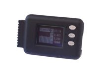
I recently got a couple of CellLog 8M units for testing. The 8M is similar to the 8S, but much cheaper and does not have a logging funtion or USB interface.
Here is the User's Guide:
View attachment CellLog 8M.pdf
Of particular interest to me was the layout of the power supply inside the CellLog.
The current drain of the CellLog is such that if you always left it connected to the pack, it will drain the cells fairly quickly and somewhat unevenly. My goal is to find a nice way to turn it off without unplugging it.
The front end/ power supply arrangement is interesting. There are diodes on each input the direct voltage to a linear regulator that supplies 3.0v to run the MCU and display backlight. The MCU is an Atmel ATMega32.
Cells 1 and 2 feed their voltages directly to the MCU through some resistors.
The remaining cells go to differential amplifiers that take the difference between inputs and reference them to ground for direct input to the MCU.
Cells 3 to 6 go into a LM324 quad op amp that is powered by a feed from the diodes on those cells.
Cells 7 and 8 go into a LM358 dual op amp that is powered from the diodes on those cells. Since the LM358 has a maximum supply voltage of 32v, they put the power ground of the LM358 to the 3v supply instead of to ground. This gives it a little more 'headroom' in the voltage rating.
By disconnecting pin 0 (pack -) connection, the unit can be largely turned off, but the op amps are still draining the cells to some extent.
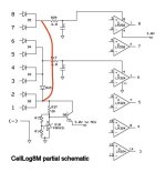
Here's a partial schematic showing the power distribution inside the CellLog: Not shown are the input resistors going to the op amps. Also note: the op amps are not necessarily shown in the right order.
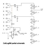
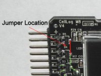
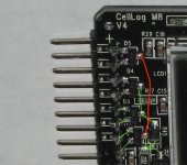
The dashed red line shows the location of the jumper needed to 'even out' the current drain on the CellLog as figured out by guys on the R/C forums.
Without the jumper, cells 1-6 will be drawing more current than 7 and 8, resulting in unbalanced cells over time. By adding the jumper, the drain is more evenly distributed on the cells.
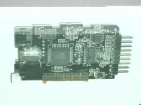
Here are some shots I took of the board. It's really hard to trace the circuits because the solder mask is black. If you hold the board up to the light at just the right angle, you can sort of make out where the traces run.
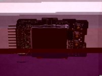
(Click picture to enlarge)
I recently got a couple of CellLog 8M units for testing. The 8M is similar to the 8S, but much cheaper and does not have a logging funtion or USB interface.

Here is the User's Guide:
View attachment CellLog 8M.pdf
Of particular interest to me was the layout of the power supply inside the CellLog.
The current drain of the CellLog is such that if you always left it connected to the pack, it will drain the cells fairly quickly and somewhat unevenly. My goal is to find a nice way to turn it off without unplugging it.
The front end/ power supply arrangement is interesting. There are diodes on each input the direct voltage to a linear regulator that supplies 3.0v to run the MCU and display backlight. The MCU is an Atmel ATMega32.
Cells 1 and 2 feed their voltages directly to the MCU through some resistors.
The remaining cells go to differential amplifiers that take the difference between inputs and reference them to ground for direct input to the MCU.
Cells 3 to 6 go into a LM324 quad op amp that is powered by a feed from the diodes on those cells.
Cells 7 and 8 go into a LM358 dual op amp that is powered from the diodes on those cells. Since the LM358 has a maximum supply voltage of 32v, they put the power ground of the LM358 to the 3v supply instead of to ground. This gives it a little more 'headroom' in the voltage rating.
By disconnecting pin 0 (pack -) connection, the unit can be largely turned off, but the op amps are still draining the cells to some extent.
Here's a partial schematic showing the power distribution inside the CellLog: Not shown are the input resistors going to the op amps. Also note: the op amps are not necessarily shown in the right order.

The dashed red line shows the location of the jumper needed to 'even out' the current drain on the CellLog as figured out by guys on the R/C forums.
Without the jumper, cells 1-6 will be drawing more current than 7 and 8, resulting in unbalanced cells over time. By adding the jumper, the drain is more evenly distributed on the cells.
Here are some shots I took of the board. It's really hard to trace the circuits because the solder mask is black. If you hold the board up to the light at just the right angle, you can sort of make out where the traces run.

(Click picture to enlarge)


