PhoenixOSU
100 W
I've been working on a 48V BLDC motor controller to use in my moped project (because I think I can do a pretty good job and its fun). The goal is to get it working and integrate the 12V dc-dc into the controller and have the design be a prototype for a 72V design down the road. My hope is to get it to handle a peak output of 6-8 kW, and 4kW continuous, which should not be to hard, its all about the right FETs and PDB layout (I've seen some utterly vile layouts of MOSFET arrays).
I've broken it into 5 pieces
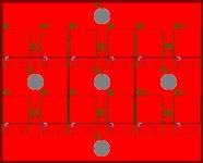
1: FET bridge consisting of 6 FETs and 6 diodes
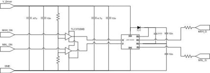
2: FET driver probably using LT4444s
3: PIC 24F series micro controller to control everything
4: Internal power supply for 12V and other logic rails
5: misc input signal processing and protection circuitry
I plan on using the IRFS3006-7PPBF MOSFETs as they are rated to 60V (I can protect them with a TVS), and some nice high recovery speed diodes for the bridge. A lot of people seem enamored with the IRF 4110 and similar FETs, why is this? Is it becuse people like the TO-220 package for easy heat sink mounting? I'm a fan of surface mount parts because you get more flexibility in layout and can use the PCB itself to help with heat issues, I'll still mount a big old copper heatsink on it.
For drivers I'm divided and would like some input, I like the LTC4444 because it is well documented and has a spice model that I trust, but there are other options out there that can outperform it, such as the FAN7390M, which has little to no documentation which makes me more nervous about it.
I am curious about the PWM frequencies that people are using for BLDC motors, I plan on using something around 80KHz, low for a switcher, but above the range of human hearing, the lower you go the less loss you have due to switching times, and less need for a massive driver, and I've noticed that some controllers use 18 FET arrays (3 parallel), which seems to indicate a low PWM frequency. I have developed an excel table for comparing FET efficiencies, I wouldn't use it for accurate power loss estimates, but for rough numbers, and to compare FETs in "all else being equal" situations, and also to see which parameters have a bigger effect on efficiency. Paralleling FETs halves the on resistance but doubles the gate capacitance, a trade off that may or may not work in my favor depending on several things mentioned earlier.
I don't plan on selling my design, just using it and giving the design files to anyone who wants them.
I've broken it into 5 pieces
1: FET bridge consisting of 6 FETs and 6 diodes
2: FET driver probably using LT4444s
3: PIC 24F series micro controller to control everything
4: Internal power supply for 12V and other logic rails
5: misc input signal processing and protection circuitry
I plan on using the IRFS3006-7PPBF MOSFETs as they are rated to 60V (I can protect them with a TVS), and some nice high recovery speed diodes for the bridge. A lot of people seem enamored with the IRF 4110 and similar FETs, why is this? Is it becuse people like the TO-220 package for easy heat sink mounting? I'm a fan of surface mount parts because you get more flexibility in layout and can use the PCB itself to help with heat issues, I'll still mount a big old copper heatsink on it.
For drivers I'm divided and would like some input, I like the LTC4444 because it is well documented and has a spice model that I trust, but there are other options out there that can outperform it, such as the FAN7390M, which has little to no documentation which makes me more nervous about it.
I am curious about the PWM frequencies that people are using for BLDC motors, I plan on using something around 80KHz, low for a switcher, but above the range of human hearing, the lower you go the less loss you have due to switching times, and less need for a massive driver, and I've noticed that some controllers use 18 FET arrays (3 parallel), which seems to indicate a low PWM frequency. I have developed an excel table for comparing FET efficiencies, I wouldn't use it for accurate power loss estimates, but for rough numbers, and to compare FETs in "all else being equal" situations, and also to see which parameters have a bigger effect on efficiency. Paralleling FETs halves the on resistance but doubles the gate capacitance, a trade off that may or may not work in my favor depending on several things mentioned earlier.
I don't plan on selling my design, just using it and giving the design files to anyone who wants them.