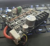
My Brushless Design for Hall Effect Type Motors, Looking for Suggestions

Botvink

1 mW
Joined
Jan 26, 2023
Messages
18
Hello friends,

I'm very new to the forum, but I wanted to contribute a little and share the project's changelog and get your valuable friends' ideas.
I design mostly brushed motor drivers, controllers for years and trying brushless motor designs, that design is my 4th attempt and at every update I changed.

Designed for max 6S lipo up to 200A current if possible, but first I plan for healthy 50A continous currents.
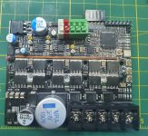
bls-unity.jpg

It is 4 layer board with NXP LFPAK88 mosfets and PSOC based controller. I will list items generally:
  • Mosfet drivers are IRS21867 x 3, happy with them. :)
  • Bootstrap diodes are SBRT3U45SAF-13 Super Barrier Rectifier, I had clues about shotky type or SBR diodes arebetter but used at controller and didn't see any much difference.
  • Bootstrap capacitors are 2.2uF 100V X7R type.
  • Controller is CY8C4245-AXI473, I choosed PSOC because I am only experienced on it, also using schematic design, Lookup tables, PWM blocks very easy.
  • Mosfets are Buk7s1r0-40hj 40V 325A models with paralled x 2 for every channel.
  • For 3 outputs I added MOV and TVS to power lines. also at main power line 1 x TVS added.
  • 3 Temperature sensors added middle of mosfets. LM60BIM3 basic Sot23 sensors.
  • Gate resistors are 10 ohm (anti paralleled with shotky) + 10 ohm.
  • Bootstrap return path has 4.7ohm resistors with shotky diode.
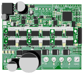
board.png

As it is low voltage driver I thought linear regulators can be enough. But it heats up quickly.. I guess I will change for next update.

As my aim is using at battle bots, combat robots which need full fast forward backward speeds, and high torques, sometimes up to stalls, I didn't planned to integrate FOC or sensorless control (though I don't have much knowledge about Foc..:))

Current sensor was ACS780 50A model. I planned to use higher current but out of stock. But while making tests with this current sensor It started to give faulty values and peak current signals as normally motor was driving at 3A, I read from console nearly 100A. I guess these ACS78x models are not suitable for inductive type forwars backward movements.. Some hall element inside broken or calibration broken..


So at next version I planned:

- Change Ground plane, traces with bigger, as it was my 1st 4 layer board, I didn't made power circulation well.
- Updating regulators (still my max voltage will be 6S lipo but it needs better ICs sure.
- Finding noise immune current sensor, Maybe ACS758?
- Top layer, power side will be unmasked.
 
Last edited:
Hi and welcome, great to see even more people attempt to build controllers!

You've got very high density so rearranging is going to be a lot of work. Nevertheless, you asked for ideas/opinions.

Normally we sense on the phases, more flexible that a single high side current sensor.

You're routing your analog signal right under your power stage. Might explain the random 100A readings, except that with those sensors 50A... You cannot read 100A so I guess you have a software fault.

In general your layout should probably be upside down... That is... Ground of the FETs next to the micro not Vbat next to the micro. As it is now, your ground reference is the opposite side of a load of noise. I made this mistake on my first boards, it worked surprisingly well considering, but there's definite ground bounce.

The capacitors from switch node to ground... why? Normally we do not do that since it's inefficient and all that loss goes directly into the mosfet junction. If you have problems with ringing, we would tend to put a series resistor with the capacitor to act as a snubber (damper).

What's going on with the bonus MOSFETs next to the high side FETs?

Lastly, nexperia are outright liars with their specs. They lure you in with nonsense lies and a proprietary package that forces redesign to change or compare to other brands. The current ratings they claim couldn't be carried by an equivalent size copper bar. I'd be inclined to swap to a more interchangeable dfn package from on semi or infineon/1000 different Chinese replica options.
My fault, switch node to ground yellow components are MOVs (28v rated), not capacitors. as they use same pattern it looks like caps :) I should add also RC snubber placements for next update. At these design i paralled mov and tvs for each swtich node.

It is true that at current sensor reading i have some problem.. Because changed it with acs758 but still problem persists. Actually i can add software filters but filters will add delays. And i dont know how much delay is too much. Now my one control cycle taking 190uS.

Adding phase current sensors is better sure i should consider but routing to small area little scares me.

Upside downing layout can be made but i didn't understand the effect much. And again if i revert position i shouldn't connect power gnd and logic gnd isn't? they should be attached at only one point.

At past i used also that Psof-8 mosfets, but i dont know.. nexperia values fascinated me. And paralleling 2 x lfpak88 may be better than 1 psof for this size..
 
The ACS current sensors should be pretty noise immune but the traces may not be. It sounds like it's reading outside the ADC range though.

By upside down i just mean getting the ground side of the mos next to the logic. As it is now you have power and logic all over the board, you could separate them better. But it seems to work so maybe fine.

190us is very slow for a control cycle. At 48MHz that's 9000 clock cycles. This is probably because you're accidentally using floating point numbers (or even worse it's promoting them to doubles) on a processor that doesn't support floats. You might have to take the pain of converting all your units to int...

Also, make sure the compiler optimiser is turned on. If you're using GCC work out how to enable o2.

Good luck!
 
Thanks! Very good ideas. And I made turned on optimiser, it changed. And yes I was making float calculations which is not supported as default. Though float variables, bloats the code also but I didn't know it can affect cycle time. Learning from good experiences :)

I changed current sensor with ACS758KCB-150CB, that beefy type 150 Ampere bidirectional sensor that I saw also many designs using it. BUT, again these sensors blow up twice!

After hard brakes and reverses; sensor's calibration broken, we recalibrate at software and after few tests, sensor voltage output directly gives 0V. I don't understand how hall element inside can be broken. I was very disappointed from allegro current sensors. I changed again and also made copper bar paralleled for current sharing but not much luck, It is not %100 safe solution.. Searched net, I guess at past one similar problem happened too: Problems with ACS758 Hall Effect Current Sensors - Calibration and no Signal

BTW, except current sensors I didn't need to change any other components, or never resets happened. If Resets happens or PSOC burns I would suspect 5V line..

For current sensor problem I plan to use non-intrusive type sensor, that I found at Aliexpress, this is tiniest:


This is current state of project.


Here, we test with some e-skater motor 5055 type. at 6 cell lipo. Free load 3A, at starts & stalls it draws more than 70A (I guess, coil resistance is 100milliohms).
 
Last edited:
I wanted to add little update.

I modified with WCS1700 sensor, it works well as planned for now. But current signal is noisy as usual.
My one cycle time is now like 50uS. At one cycle I can measure VBus, Temperature sensors and Current sensor analog inputs and update PWM signal if change happened.

So my question is 50uS 1 cycle time good time for current control? For meaningful filtering I should use more samples at least 10 sample, and at 500uS will my mosfets can withstand to overcurrent situations. I don't know...

Usually mosfet datasheets giving information for that overcurrent situations at 1uS time durations..

bldc-update.jpg
 
Hi again!

500us is plenty of time to kill your MOSFETs if you get an excess Vbus or large overcurrent. More typical is sub 50us which can save most faults.

Are you synchronising your ADC readings with the pwm? If they're asynchronous you'll find you get lot of noise on them.
 
Back
Top