The badnews graph: Other way looking at LFP's reality check

jag

10 kW
Joined
Feb 16, 2009
Messages
777
In the **Important** reality check on motor, voltage, current etc. thread LFP/Luke, Rhite05/Eric and others are doing an excellent EE-based description of the power conversion in a switched regulator.
http://endless-sphere.com/forums/viewtopic.php?f=2&t=19590&start=0

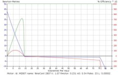
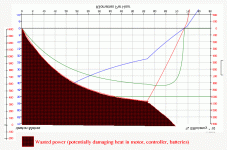
A bit of a different and more overall take on this topic is to look at overall power instead of the details of the PWM switched voltage and currents. After all what burns things is heat and heat comes from dissipated power. An overall look at wasted power is surprisingly easy to obtain from the ebikes.ca simulator. Just turn the graph upside down, and adjust the power scale for the motor efficiency. See example below for my 9C and 20A analog controller:
badNewsXFig.gif
Conclusion is essentially the same as in the realitycheck thread: there is a large wasted power in the low and medium speed ranges where the cpontroller is PWM switching the voltage down and current up and therefore the Ri of the motor is a dominant source of waste heat (with lesser/insignificant contributions from battery and controller also included in the graph).
 
Yes!

This is why the RC guys are in love with throwing a 10:1 or 20:1 or whatever reduction between the motor and wheel, so we can get into the efficient part of the curve as soon as possible.

Every motor has 0% efficiency at 0rpm, but some can climb quickly away from that low efficiency by 5-10mph (depending on gearing of course), where a direct drive hub pretty much just has to suck it up and be more heater than motor until they get up to high speed.
 
LFP, I'm embarrassed to confess I still don't have a grasp on what this means in plain english (your posts sound like you undestand this). Would RC controllers fry less if they had a 3-sp hub as a transmission? or should top-speed/motor/ESC/voltage combinations just be matched within a narrow performance band?

If yes, could somebody with a grasp of this post some type of a chart with JUST a handful of "likely to be successful" combinations. "A"-MPH using "B"-kW's worth of power will need....Motor "X", ESC "Y" using "Z"voltage = reliable RC combination.

I want to be 30-MPH capable, but will likely spend most of my time at 25-MPH, with lots of stop-n-go. 1kW perhaps?
 
Batteries are already cheap enough for 2/3 wheel EVs to make sense, and electricity is cheap, so efficiency is down near the bottom of my importance list. Plus it's only an efficiency difference for less than 100 yards. I ride at 35-40mph at 50wh/mi, and my motors are current hogs, so I question the real world efficiency gains of more turns in the windings to go the speeds I need.
 
John in CR said:
Batteries are already cheap enough for 2/3 wheel EVs to make sense, and electricity is cheap, so efficiency is down near the bottom of my importance list. Plus it's only an efficiency difference for less than 100 yards. I ride at 35-40mph at 50wh/mi, and my motors are current hogs, so I question the real world efficiency gains of more turns in the windings to go the speeds I need.


You're right of course, once you're up to speed, it doesn't matter what things were like down low. It's mostly just a concern for an application for a bike that you want to be able to run on a long winding technical trail at walking speed, then still be able to blaze down the highway at 50mph. If you're planning mainly to just run a some certain speed, and your motors are efficient at that speed, then you don't gotta worry about the rest of the curve.
 
liveforphysics said:
Every motor has 0% efficiency at 0rpm, but some can climb quickly away from that low efficiency by 5-10mph (depending on gearing of course), where a direct drive hub pretty much just has to suck it up and be more heater than motor until they get up to high speed.

This is something that is said a lot, but it needs to be put in the context of accelerating hard with WOT. The efficiency of a direct drive hub motor can still be perfectly good at low speeds too, just back off on the throttle so that the phase current is at some reasonable value and isn't dominating the I^2R power losses.

For instance, in the graph posted by Jag, which I assume is a 2807 hub at 66V, the efficiency at 10 kph shows a pretty abysmal 17-18%. However, using exactly the same setup, with the throttle scaled back to 20% duty cycle, then at 10 kph the efficiency of the hub is running more like 66-67%, generating a full 10 N-m of torque which is way more than necessary to sustain a 10 kph speed level:
20 percent throttle.jpg

Most people ease into the throttle as they accelerate, and people riding around at low speeds on the sidewalk or whatever are being pretty light on the throttle, so to say that the hub motors are only efficient at really fast speeds is misleading.

Whether a geared R/C style motor setup or a hub motor setup will be more efficient depends only on the winding resistance of the motor. If both are configured for the same unloaded RPM, then the motor with the lower RWinding will have the better efficiency in this part of the regime.

-Justin
 
Excellent point Justin. Now if we can just figure out how to make the controllers more efficient at partial throttle with these low resistance hubs. Based on controller heat, I must be throwing away an extra 100W+ at the controller by riding only about 60kph when my bike will do 90kph. How do we get the best of both worlds with a motor that has so much less heat loss in the windings?
 
Out of curiosity I decided check my mileage at WOT, something I've never done because in my normal riding I rarely maintain a WOT throttle position for more than 10-15 seconds other than going over some long hills. My bike is just too fast for sustained WOT except on the highway. It was also a test for controller heat, controller efficiency, for WOT vs my normal riding where every controller I've used with these motors has gotten quite hot, so I taped up the wind's direct access to the controller since I didn't want it cooler just because of more wind over it at higher speed.

The results surprised me so much that I had to make a second run after ensuring everything was calibrated properly. After a year and a half of almost no changes to this bike other than changing pack capacity, I'm intimately familiar with it, and I average right at 50wh/mi in normal riding. Yes, that's high, but considering that I'm 250lbs plus a 115lb bike, brake to stop without coasting, don't pedal except taking off from 0, run 32lbs of pressure in both tires including the somewhat knobby motorcycle tire on the motor, and cruise right around 35mph (56kph), it seems like decent efficiency for the performance I get riding it more like a scooter or small motorcycle than like a bike. Slower is too slow for traffic, it's a good speed for feeling a nice cooling wind in the tropical sun, and faster speed creates wind noise around my ears that I don't like.

So I take the bike out on the highway, 5 miles out and 5 back. I feel the controller at the red light immediately upon getting off the highway, and it's barely warmer than ambient. I get home and measure what goes back into the pack for a full charge, and get 51wh/mi. I think no way! You have to understand, we're talking about a slowest speed of 50mph up a couple of slight grades and 59mph (95kph) maximum on the downside and right around 55 on the flattest sections. The wind to overcome is extremely different at those speeds than in the 30's. I wait a few hours to be sure I'm starting with everything back to ambient temps and make the same run. All WOT again and same route, but this time speed drops below 50mph a few times and max speed was 58mph. I get home and recharge and the result is 56wh/mi. I attribute the difference to a noticeable side wind on the second run that negatively affected both speed and efficiency due to increased turbulence and aero drag.

Sure the stop and go of every day riding negatively affects my mileage, but there's just no way that makes up for the wind difference. It appears that the wasted heat in the controller of partial throttle riding makes a bigger difference than I would have thought possible. It started raining, so I couldn't do a different kind of run on my normal routes, but tomorrow I'll do 15-20 miles of my normal routes (not highway) at my normal speed, but instead I'll work the throttle like an on off switch to go normal speeds but with WOT pulses and glide. My goal isn't to try to maximize efficiency, but instead to get a feel for the effect on controller temperature and mileage using a pulse and glide approach. If it seems to make a significant difference, then I'll connect up a cruise control for constant speed, and parallel a momentary switch with my throttle for real pulse and glide but same avg speed, and take it on the highway for some truly comparative runs at 35mph.

John
 
justin_le said:
For instance, in the graph posted by Jag, which I assume is a 2807 hub at 66V, the efficiency at 10 kph shows a pretty abysmal 17-18%. However, using exactly the same setup, with the throttle scaled back to 20% duty cycle, then at 10 kph the efficiency of the hub is running more like 66-67%, generating a full 10 N-m of torque which is way more than necessary to sustain a 10 kph speed level:
-Justin

You guessed right on the voltage and hub I neglected to mention. Or is there some secret watermarking in the simulator graphs ...

I agree that DD hub motors are pretty efficient on flat ground at a low and relatively constant speed. Typical routes/commutes can be more challenging than this though with hills and stop and go. I live right on the edge of the river valley here and have various hills around 5% whenever I go west or north. In particular there is a 4km one to the west that seems to suck up much battery.

I've often had the hunch that babying the DD hub up slowly is no point; better to go WOT. A simple example with your simulator seems to support this:
I need about 40nm torque for a 4-5% hill
At 30% throttle and 40nm I go 7km/h with a motor efficiency of 17%
At 100%WOT and 40nm I go 24km/h with a motor efficiency of 60%
Here no quadratic air friction is taken into account. It will be insignificant compared to the climbing work at both 7 and 24km/h.
So not only do I get up 3 time faster at WOT, but I also use only 1/3 battery energy!!
 
Another rule of thumb: Of the power put into a motor, the good BEMF*I part does the work, while the bad I^2*R creates heat. To get BEMF we need to spin the motor, and the faster the better; the ratio of good work to bad heat improves the faster the motor spins.
 
jag said:
I've often had the hunch that babying the DD hub up slowly is no point; better to go WOT. A simple example with your simulator seems to support this:
I need about 40nm torque for a 4-5% hill
At 30% throttle and 40nm I go 7km/h with a motor efficiency of 17%
At 100%WOT and 40nm I go 24km/h with a motor efficiency of 60%
Here no quadratic air friction is taken into account. It will be insignificant compared to the climbing work at both 7 and 24km/h.
So not only do I get up 3 time faster at WOT, but I also use only 1/3 battery energy!!

Hi Jag, no question at all that going up a hill fast will almost always use less watt-hours than a slow climb with the same motor gearing. You can have fun quantifying this using a CA as a speed limiter and going up the same climb again and again with increasing speed limits and monitoring how many watt-hours it takes.

But that's a different scenario than we were discussing, and doesn't mean that you are better off accelerating at full throttle instead of gradually easing on the throttle. When you accelerate, you are going through the entire speed range from zero to cruising rpm regardless. If you do this at WOT, then for a large percentage of the acceleration the motor efficiency is quite poor. But if you are gradual with the throttle, then you've got the motor above 70% for the entire time you are building up speed.

-Justin
 
Justin,

That's very interesting. Have you actually measured that the gradual acceleration is indeed more efficient? I thought the PWM of the controller automatically made the voltage seen by the motor increase gradually with speed as a result of current limiting. That would make fun acceleration free other than the slight wind cost of higher average speed by getting up to speed more quickly.

I want to figure out a way to quantify the difference, because I want to get one of my bikes to amusement ride status, but if it shoots half of my pack capacity that would take away from the fun.

John
 
I guess it would depend on what your current limits are set to. If the manual gradual acceleration restricts current to a significantly lower limit than the controller's limit does, you'd see a power savings (but not as fast an acceleration).


These are more things to consider for that whole-bike computer-controlled system I would still someday like to design. Have user-selectable acceleration curves pre-programmed into the controller that allow this sort of thing.

Also, since it would have an accelerometer built in, it could tell if it was accelerating fast enough and attempt a bit more power to see if it helps, and if it doesnt', then cut back on the power until the acceleration begins to drop off, then go back up a tad, so power's not being wasted as heat quite as much.

Another use for the accelerometer is to detect when it is going uphill vs downhill, and the slope, and control acceleration/throttle curves appropriately.
 
Sooo...the thing that frying all the RC build controller FETs is a low-volt, high-amp system that is lugging the small motor while accelerating from a stop...(spending lots of time at full throttle and low-RPM's?)
 
spinningmagnets said:
Sooo...the thing that frying all the RC build controller FETs is a low-volt, high-amp system that is lugging the small motor while accelerating from a stop...(spending lots of time at full throttle and low-RPM's?)


Yep, pretty much. Any controller can suffer from this, not just RC style. Multiple speeds would reduce the starting amperage greatly, so a three speed would indeed be a good idea.
 
johnrobholmes said:
spinningmagnets said:
Sooo...the thing that frying all the RC build controller FETs is a low-volt, high-amp system that is lugging the small motor while accelerating from a stop...(spending lots of time at full throttle and low-RPM's?)


Yep, pretty much. Any controller can suffer from this, not just RC style. Multiple speeds would reduce the starting amperage greatly, so a three speed would indeed be a good idea.

It has less to do with it being low volt, and more to do with the motor's low resistance and an ebike's riding profile. Less resistance = greater phase currents, and a heavier load like an ebike spends far more time in the "high phase current" area than a plane propeller. Also, unlike a propeller, phase currents may go up no matter the throttle/duty cycle due to increasing physical loading (Like going up a hill) while the same isn't true of a propeller. Lower throttle = less propeller speed = less phase amps, almost always. Given these differences, greater controller cooling is needed.

That being said, it seems the common factor among ESCs that survive is high gearing, that way the motor can get out of the high phase current area as quickly as possible. If it's geared too low, the phase currents will be higher for a longer period of time, resulting in prolonged ESC heating = destruction.
 
amberwolf said:
... If the manual gradual acceleration restricts current to a significantly lower limit than the controller's limit does, you'd see a power savings (but not as fast an acceleration)...

Justin may be an ebike god, but for me the jury is still out on this one. It's not like an ICE motor, and to accelerate to a certain speed requires a fixed amount of energy whether you do it quickly or slowly (ignoring the difference in wind's effect). The inherent current limiting also provides a gradual ramp up of voltage to pack voltage as well. Even if it costs an extra 1/10th of a penny per acceleration, who cares? That's $10 for 10,000 erocket bike amusement ride takeoffs, what a bargain.
 
Yes, if you can't launch it hard, and accelerate hard anytime you want, it would have no appeal to me. :)

But if you're just trying to commute with the smallest battery size and have a very reliable setup, that's a whole different gig. :)
 
John in CR said:
amberwolf said:
... If the manual gradual acceleration restricts current to a significantly lower limit than the controller's limit does, you'd see a power savings (but not as fast an acceleration)...
...to accelerate to a certain speed requires a fixed amount of energy whether you do it quickly or slowly (ignoring the difference in wind's effect). The inherent current limiting also provides a gradual ramp up of voltage to pack voltage as well.
The "requires a fixed amount of energy required" part is right, but the point that amberwolf and justin are trying to make is that your motor will be converting less of the total electric energy to mecanical energy if you accelerate harder (lower efficiency with higher phase currents), so it will effectively take you more energy to get to the same speed when doing it faster.

The best thing would be to have a two mode current setting switch, so you could have a low current "watt miser" mode and a "full power" mode. I am not certain if this has been attempted by anyone on an infinion/XC116 controller? The low current setting would avoid having to pamper the throttle, which is very sensitive due to it's PWM duty-cycle based control method.
 
Pat,

I understand that higher phase currents increase copper losses, but it also occurs for a shorter duration. Also the lower duty cycle increases losses in the controller as an offset. I suspect the effect on overall efficiency is tiny as would be the difference in losses to the wind of a slightly higher average speed. I want to try to quantify this with some real world testing, because I firmly believe the more exciting riding an ebike is, the quicker they will be adopted in the mainstream. If the difference is small, then it should be a selling point and forget about encouraging people to accelerate slowly in the name of conservation.
 
My reason to accel slowly is to save battery so I can carry a smaller (lighter) one to get the same range and haul more cargo with it. Or to get a longer range from the same battery. ;)

I'm not after the exciting build, at least not for a street-legal one. Now, for a death-race version, I don't care about saving the battery power. :lol: Maybe for a demo bike to show others what an ebike can do and still be reasonably safe and legal, I'd also go for the exciting version, but again it wouldn't be a long-range bike, just a short demo.

I do like fast acceleration, and with the 9C on DGA I've been using it on my short work commute, but sparingly as it's reallly hard on the NiMH. (that's one more reason to accel slowly, I guess, but not my primary one). If I do a longer trip, like if I plan to take a grocery run after work on the way home, it's enough extra distance and power needed for the extra load that unless I carry the larger NiMH as a spare I need to keep the accel slower to leave me enough power to be able to accel without much pedalling (or it hurts my knees too much with that kind of a cargo load in there).


So there are reasons for each type of need, and if I could I probably would use the harder accel just because I can. :) I even like being able to wheelspin from a stop but it's pretty hard on tires so I would rather not do that very much. ;)
 
Something else to considder, Justin found those magnetic flux saturation limits for the 9x7's 9C's stator teeth at something like 80-90phase amps if I'm remembering correctly. If you're pushing current past that point on a 9c, you're causing a ton more heat in exchange for very little additional torque.

I don't know where the limits are for the 530x series, but setting phase limits to be above that saturation point is kinda just an exercise in heating the motor/controller, and wasting pack energy.
 
liveforphysics said:
Something else to considder, Justin found those magnetic flux saturation limits for the 9x7's 9C's stator teeth at something like 80-90phase amps if I'm remembering correctly. If you're pushing current past that point on a 9c, you're causing a ton more heat in exchange for very little additional torque.
Very good point - And it's not hard to get phase currents up to 100A at low speeds.


liveforphysics said:
I don't know where the limits are for the 530x series, but setting phase limits to be above that saturation point is kinda just an exercise in heating the motor/controller, and wasting pack energy.
Any chance of someone doing the magnetic saturation test on an X5? Any guesses on possible numbers - around 150Nm maybe? I'm sure there are more than a few people pushing their hubs way past this point of little return without knowing it... I know I was.
 
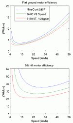
In the first post of this thread the power loss graph as a function of speed at full throttle was shown. Justin pointed out that for most riding this is not relevant. To calculate the motor efficiency in a more realistic way the power needed to sustain a particular speed must first be calculated, and then the torque/current of the motor needed to produce this power, and finally the losses incurred. I wrote a m-code script (attached at end) to do this, and calculate percentage motor efficiency as well as Wh/km for the three motors I have; a 9c, BMC V2 and Astro 8150. These are also representative of the better motors in the three classes direct drive, geared internal hub and geared RC setup respectively.

The calculations assume a total weight of 100kg for bike and rider, on an efficient bike, that is using low rolling resistance tires (slicks or semi-slicks and having a small air friction (riding semi-crouched or crouched on an aerodynamically efficient bike). Two examples are graphed: Flat ground riding and a 5% hill. Normal riding is likely a combination of some flats and hills so contained in between these two conditions. The graphs for less efficient bikes will have the same general shape, but numbers/scale will be different.

The first graph illustrates the percentage efficiency. Only I^2R losses of the motor (see below) and a common 0.01Ohm controller are included. There are also dynamic switching losses and mechanical losses, but I believe these are typically smaller in magnitude. (e.g. chain or belt drive for an RC motor or planetary of a geared hub motor are usually 95-98% efficient, and efficiency does not vary (much) with speed, so they would merely translate the graphs 2-5%, but not change the general shape. Losses due to AC switching waveform I'm guessing are also below 5%)

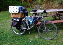
In flatland all the motors are quite efficient for most speeds (around 80% or better). However in hilly terrain there are significant differences. It should be noted that a 5% hill in my experience is about the upper limit for my 9C motor pushing me and the bike. Riding in the efficiency sweet spot between 20 and 50km/h requires 40-60A phase currents. In practice my 9C gets warm but not hot to the touch at these amps. Above 60A the 9C goes non-linear as Justin has shown, and currents above 60A result in a higher proportion heat. When I need to carry additional weight I have to adjust my riding to avoid hills. For instance today when unloaded I took the scenic, but hilly bike road in the river valley to the grocery store. On the way home, when I was loaded down with two full panniers and a box on the rack (see picture below) I chose a route back on the flat prairie. The calculations and graphs also echo the experimental findings that Ilya and others have made: In hilly San Fransisco the geared BMC v2 motors work better than DD. Finally the RC motor is running only at about half load in the 5% hill condition. Due to its higher efficiency (bit more torque per amp) it uses 36A at 20km/h and 55A at 50km/h. Astro rates it for 90A continuous.
file.php


From the point of view of battery needs, evaluating Wh/km is more relevant. This reweighs the graph above to reflect the lower power need at slow speeds. (Since only a little output power needed at slow speeds it matters less that the motor is ineffient at slow speeds.)

Again, on flat ground all motors are efficient over a wide range of speeds, while on hills there are differences. The 9C has to get up to 20km/h to be reasonably efficient while the geared hub and RC has a wider efficiency range starting at below 10km/h. With the 9C this is also very evident in practice. If one goes too slow in a misguided attempt to save battery energy the opposite happens, and the battery runs down faster (guess how I know -- it always seem to happen when the rain is pouring down too). However tackling a hill at efficient speed with the 9C takes a battery and controller that can deliver from 1kW (20km/h) to 2kW (50km/h). (The 9C motor itself seems to be fine at up to 2kW input power even though it is only a "500W" motor).

Note: The two graphs below would perhaps better be titled "Specific energy use" to distinguish them from the graphs above. However it is too much work to redo them just for changing the title.
file.php


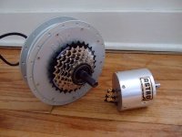
Edit 1: I added some pics and info on the motors. Worked in some more details in text above also.

Every motor creates force by having a current carrying wire pass through a magentic field. The magnetic field is created by permanent magnets in these motors, and good motors use rare earth magnets which is as good as they get today. (Motors in e.g. consumer products commonly use cheaper ferrite magnets.) The essential difference between the three motor types is the relative linear speed of the wire in the magnetic field compared to the linear speed of the bike wheel.

The NineContinent (9C) is a good representative of a direct drive (DD) hub. In this case the motor is fixed to the wheel so one motor turn is one wheel turn. Since the motor has to be contained inside the wheel the linear speed of the magnet wire is by necessity smaller than that of the wheel. The 9C motor is about 200mm in diametre. Making them bigger would make them too heavy. Many other companies make DD hubs, but the 9C is AFAIK the one with the best aspect ratio (large diametre compared to relatively narrow rotor to get good torque at relatively low weight. E.g. Crystalyte have smaller aspect ratios and therefore weigh more for a given torque capability)

The BMC V2 is a good representative of an internally geared hub motor. The motor power is transmitted through a 5:1 planetary reduction gear, so for each 5 motor turns the bike wheel turns once. Another way to look at this is that while the motor is smaller that the 9C, and in itself generates a smaller torque, the torque is amplified by the gearing so that it is equivalent to a DD hub that is larger than the wheel. (This of course also means that the motor turns faster but that is ok -- they are efficient at high rpms). Similar motors are EZee and MAC Shanghai, and PUMA/BMC V1. They have slightly higher internal resistance and are a a bit lighter, so I'm thinking they may be slightly less tightly wound with magnet wire than the BMC V2.

The Astro 3" motors is representative of a good RC motor. Here one has to add an external transmission oneself. Luke/LFP uses chains, Grinhill and I use a single stage 9mm wide HTD toothed (timing) belt transmission. Recumperence and others use multi-stage belt-chain combinations. An advantage is that a much wider ratio of gearings are possible than with the built in planetary of the hub. This means that a small, fast turning motor can be used. E.g. my Astro 8150 weighs only 1.5kg and is rated at 5kW output power (6kW in). By comparison the BMC weighs 4.5kg and the 9C about 6kg and while rated at 500-600W these are both capable of about 1 to 1.5kW output power (with up to 2kW input). (In the 9C limited by thermal wiring losses and the BMC the quality of the one-way bearing and gears.)

dsc_0024_sm.JPG

file.php


I tried to upload the source code file, but the server said it was a non-allowed file type. Here it is inlined for the curious. I tested the code with both Octave and Matlab. Octave is free. Might run with Scilab and the many similar calculation packages also. For Linux/Fedora just do
Code:
yum install octave
. For windoze you have to download and install manually or pay.
vk = 10:10:50; %km/h
v = vk./3.6; % m/s
dH = .05; % Hill rise in %/100 Steep hill
%dH = 0; % Hill rise in %/100
m = 100;
g = 9.81;
% Crr = 0.004; % Slick road tires
Crr = 0.008; % Semislicks
% Crr = 0.013; % Knobbies
% CdAlbf = 0.0036; % Full crouch
CdAlbf = 0.004; % Straight arms
CdA = CdAlbf*.454*g/.3^2; % Convert to metric

% Power in watts to sustain speed v:
Pb = CdA.*v.^3+(Crr+dH)*m*g*v;

k = 1.07; Rmotor(1)=0.231; A0=0.54 ; motor = 'NineCont 2807';
%k = 0.89; A0=0.905; Rmotor = 0.07; motor = 'BMC V2 Speed';
%k = 24*0.048; A0=24*0.048; Rmotor = 0.040; motor = '8150 5T, 1:24gear';

Rcontroller = 0.01;
d = 0.655 %Wheel diametre

% Current needed into motor to get Pb at wheel:
Im = d*(Pb./v + A0)/k;

Ploss = Im.^2*(Rmotor+Rcontroller);

Ptot = Pb + Ploss;

% Motor efficiency in percent
Meff = Pb./Ptot;

% Energy needed to go 1 km (Wh/km)
Ed = Ptot./vk;

MeffM:),3) = Meff;
plot(MeffM)

EdM:),2) = Ed;


plot(Meff)

subplot(221)
%subplot(223)
%plot(vk, Ed);
plot(EdM)
xlabel('Speed (km/h)')
ylabel('(Wh/km)')
%legend('NineCont','BMC V2','Astro 8150, 1:24gear')
title('5% hill motor efficiency')
print('Meffgraph.png','-dpng')


% Attempt to calculate k from measured values
data8150_5T = [
32 , 22 , 700 , 5200 ,
42 , 38 , 1600 , 6000 ,
52 , 58 , 3050 , 8200 ,
32 , 27 , 850 , 5000 ,
42 , 49 , 2050 , 6500 ,
52 , 75 , 3900 , 8000 ,
32 , 35 , 1100 , 4800 ,
42 , 63 , 2650 , 6300 ,
52 , 90 , 4700 , 7800 ];

T = data8150_5T:),3)./data8150_5T:),4)*60/2/pi
k = T./data8150_5T:),2)

% 197 rpm/v -> 60/197/pi/2 Vs/rad = 0.048
% 0.040 ohms
% 1 amp


Astro 8150-5T tested with an 18x10 APC-E prop
Volts Amps Watts Rpm
32 volts 22 amps 700 watts 5,200 rpm
42 volts 38 amps 1,600 watts 6,700 rpm
52 volts 58 amps 3,050 watts 8,200 rpm
Astro 8150-5T tested with a 20x10 APCE Prop
Volts Amps Watts Rpm
32 volts 27 amps 850 watts 5,000 rpm
42 volts 49 amps 2,050 watts 6,500 rpm
52 volts 75 amps 3,900 watts 8,000 rpm
Astro 8150-5T tested with a 22x10 APC-E prop
Volts Amps Watts Rpm
32 volts 35 amps 1,100 watts 4,800 rpm
42 volts 63 amps 2,650 watts 6,300 rpm
52 volts 90 amps 4,700 watts 7,800 rpm

Luke/LFP also suggested analyzing what happens when one accelerates repeatedly in e.g. stop and go traffic. Does it matter whether to go WOT from the start or baby the throttle? However now it is midnight and the wife gets angry when I spend hours on ES (her sitting in front of facebook is somehow ok :| ) I'll leave the acceleration analysis for someone else.

Edit 2:
The bicycle drag and power calculations were reworked from:
http://www.mne.psu.edu/lamancusa/ProdDiss/Bicycle/bike calc eqs.pdf
The motor equations are on: http://www.ebikes.ca/simulator/

A good size load from the grocery store.
file.php


Every baby knows you need good batteries.
file.php


Helping with the bike trailer http://endless-sphere.com/forums/viewtopic.php?f=3&t=14660&hilit=+schwinn#p259258
file.php


Below the graphs for some reason show up again. I didn't like the scrollbars they show up with when inserted with "attach" so I used "img" instead, but somehow the attach images didn't go away.
 

Attachments

  • Meffgraph.gif
    Meffgraph.gif
    9 KB · Views: 2,566
  • whgraph.gif
    whgraph.gif
    9.7 KB · Views: 2,566
  • DSCF6030_sm.jpg
    DSCF6030_sm.jpg
    61.8 KB · Views: 2,486
  • DSCF4726_sm.JPG
    DSCF4726_sm.JPG
    91.5 KB · Views: 2,483
  • dsc_0694_sm.jpg
    dsc_0694_sm.jpg
    31.9 KB · Views: 2,483
  • dsc_0703_sm.jpg
    dsc_0703_sm.jpg
    69.3 KB · Views: 2,483
Back
Top