Brake lever types, pedelec and cruise wiring

NeilP

1 GW
Joined
Nov 27, 2010
Messages
5,012
Location
49.17303, -2.05354 Jersey, Europe
I have a 72 v 48 amp Xlyte controller, working fine with 3 way switch

I have 3 extra plugs. B, C, D But they do not match what I have on brakes, pedelec or cruise
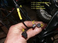

plugs labeled.jpeg


The cruise plug on the controller is B above...4 pin on 5 pin connector

Cruise switch
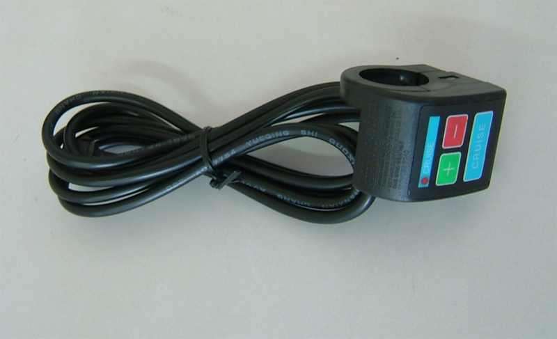
cruise.jpg


Cruise switch wires
View attachment 2

How does the cruise system work? any one got any ideas?


Could probably guess the pedelc system but would like to be assured that I am correct before I do it

Pedal assist is like this
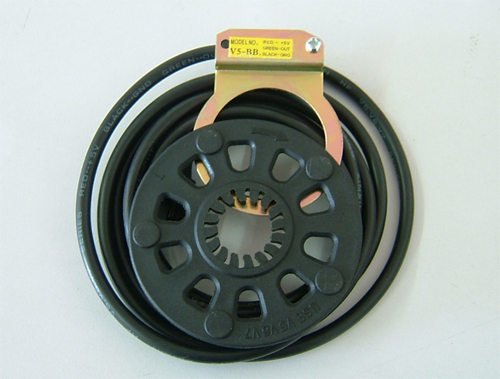
PAS_sensor_v5.jpg


Pins are not in a plug. three of them, yellow, black and red from sensor
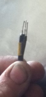
pedelec pins.jpg

Three pins on the controller plug C

Guessing, ground, 5volt and return...Is the pedal sensor a hall effect system? sending out pulses...on the yellow line?


The brake levers are 2 wire on/off switches, but brake connector is 3 wire. I have hydraulic disks now, so will need to make something up, but what are the three wires from brake connector? How is that wired...can e-btakes have a hall system as well? Ground, 5 volt and signal?
 
Maybe ebikessf can help you out with this.

Here's a link with some Clyte connector info that might useful.

http://ebikessf.com/technical/crystalyte-35a-controller-connectors


As for the pedelec system, I think I read somewhere that these can sometimes be an "on-off" type of thing with on=full power (this could have been on a Golden Motor PS though). IIRC, the GM PS would only give a regulated "throttle response" when the thumb/twist throttle was applied yet, would revert back to the "on-off" operation whenever the thmb/twist throttle was "closed". The guy that was working on it finally gave up and switched back to the non-PS setting. However, I guess you could (if needed) wire a switch onto the thmb/twist throttle housing as a means of shutting off the PS whenever the thmb/twist throttle was closed.
 
NeilP said:
I have a 72 v 48 amp Xlyte controller, working fine with 3 way switch

I have 3 extra plugs. B, C, D But they do not match what I have on brakes, pedelec or cruise

The cruise plug on the controller is B above...4 pin on 5 pin connector

How does the cruise system work? any one got any ideas?
Let me try to answer your question one by one, let start with ebrake first and then cruise control
ebrake connector had two wire
pin 1 power 12v (positive)
pin 2 ground (negative)
pin 3 ebrake signal

You only need pin 2 and pin 3 for most ebrake sensor. If you use pin 2 & 3, you will need a reed switch sesnor. Most of cheap brake lever setup are reed switch. But here is our version, you mount it under the brake lever instead of replace the brake lever. You can also use this with hydo brake.
DSC06577 [800x600].jpgTopSideView [800x600].jpg
Alternative, you can also screw the magnet onto the brake lever instead of clamp-on like i have in the picture.


If you are going to use pin 1,2, and 3. It is best to use differ type of ebrake sensor, I have hall effect type, it require constant voltage, most of ebrake is 5v, only Crystalyte use 12v, so you will need ebrake sensor that can take 12v.
eBrake-Left [800x600].jpg
for the cruise control
cruise control had 4 wire, but install in 5 pin connector with 1 empty pin in purpose (no to conflict with 4 pin throttle)
pin 1 power 5v (positive)
pin 2 ground (negative)
pin 3 throttle signal (increase or decrease you cruise control speed)
pin 4 ebrake signal (basically to shut off the cruise and motor)

Any other question for the ebrake and cruise?

Ken
 
Hi
Thanks for that.

As I mentioned, I did wonder about a hall effect type brake, although I had never heard of such a thing. I only have on/off make break type switches on brake levers I had seen. I can easily source hall effect sensors from Farnell or similar, although just getting your ready to go encapsulated units for my hydro brakes would be easier, just need to check the output wire from controller to see which is 12 v and ground.

Will try the same on the cruise control, although as pictured, my cruise control switch has two plugs. I may just see if I can get the unit apart and see what is connected where, and then see if I can match them to the controller wiring. At least now I have an idea of what signalsto expect from each wire, i stand a fighting chance of getting it sorted.

Pedelec sensor? Hall as well? ground 12 or 5 v and return signal

Thanks

Neil
 
NeilP said:
Hi
Thanks for that.

As I mentioned, I did wonder about a hall effect type brake, although I had never heard of such a thing. I only have on/off make break type switches on brake levers I had seen. I can easily source hall effect sensors from Farnell or similar, although just getting your ready to go encapsulated units for my hydro brakes would be easier, just need to check the output wire from controller to see which is 12 v and ground.

Will try the same on the cruise control, although as pictured, my cruise control switch has two plugs. I may just see if I can get the unit apart and see what is connected where, and then see if I can match them to the controller wiring. At least now I have an idea of what signalsto expect from each wire, i stand a fighting chance of getting it sorted.

Pedelec sensor? Hall as well? ground 12 or 5 v and return signal

Thanks

Neil
The hall effect brake sensor that you see in the picture require brake cable. It is trigger by the movement of cable. It is extremely reliable. However, it is not compeitable with hydro brakes, since it doesn't had cable.

In regarding your cruise control, you have to show me the picture. If you are using the Crystalyte cruise control, they just plug and play (5 pin connector). If you have other type of cruise control, they are just simple throttle lock switch. The one from Crystalyte are much better design and more flexible, use that one.

As for pedal sensor, they are 3 pin
pin 1 positive (5v)
pin 2 ground negative
pin 3 pedal signal

there are two version of pedal sensor v5 and v7. I can't remember which is which
if you have v5 sensor, it require the controller had build-in pedal sensor, in this case, the controller usually had pedal on/off switch. The signal is quite differ
If you have v7 sensor, this sensor work exactly like throttle, 0v = no speed, 5v = max speed

Ken
 
Picture of cruise control is as pictured in my first post, the cruise control switch has two plugs as pictured, and the cruise plug on the controller is plug B in the picture

The Cruise switch has a three and a four pin plug, both male, the Controller has a 5 pin plug with 4 pins, also male, so they cant plug together. I will need to remove the plugs and wire together with other plugs
 
NeilP said:
Picture of cruise control is as pictured in my first post, the cruise control switch has two plugs as pictured, and the cruise plug on the controller is plug B in the picture

The Cruise switch has a three and a four pin plug, both male, the Controller has a 5 pin plug with 4 pins, also male, so they cant plug together. I will need to remove the plugs and wire together with other plugs
NeilP:
Whoever you get the cruise control from is playing game with you. It is not possible to have two pin or two plug. The minimal is at least 3 pin.

pin 1 positive (5v)
pin 2 negative
pin 3 throttle signal

if you have two pin, it doesn't do anything for you. That's why you are confuse with these connection.

Wait...I look at the picture again, when you said two plug, you mean one plug with 4 pin, another plug with 3 pin, am i correct? Again, whoever sold you the cruise control was wired non-standard way. You need to re-wire the cruise control to be standard 5 pin connector, but with only 4pin.

Ken
 
itselectric said:
Wait...I look at the picture again, when you said two plug, you mean one plug with 4 pin, another plug with 3 pin, am i correct?
Correct two separate plugs


itselectric said:
Again, whoever sold you the cruise control was wired non-standard way. You need to re-wire the cruise control to be standard 5 pin connector, but with only 4pin.

Ken

It came from Lyen on the forum here, and it is wired for his Infineon controller, so yes, I do need to re wire...that is the question, I need to know which wire goes to which on the Crystalyte controller

I need to know which order the wires go,there is 5 colours to connect
 
That is gettimg a bit OTT for what I was thinking about.

I am waiting for mt controller from Lyen to get back ( i fried the output mosfets) so I have a crystlyte controller at the moment, and since it has pedelec input and cruise input, I was hoping to just connect it up for now, maybe make up some patch leads to connect it all together.
 
NeilP said:
It came from Lyen on the forum here, and it is wired for his Infineon controller, so yes, I do need to re wire...that is the question, I need to know which wire goes to which on the Crystalyte controller

I need to know which order the wires go,there is 5 colours to connect
NeilP:
The question should go back to Lyen. But let's examine what you have and what you know. There are four wires for the throttle,
wire one red positive
wire two black ground
wire three (either throttle signal or voltage indicator)
wire four (either throttle signal or voltage indicator)

in you case, your cruise control had red, black, white, and yellow. So you need determine which wire is the throttle signal. My guess is yellow. you should run a voltage meter to find output voltage on yellow and white wire. Otherwise, you may blow something. Once you find out, let's assume yellow is throttle signal (0 - 5v), then, you wire the throttle signal onto pin 3 of the cruise control connector. For Crystalyte controller the standard cruise control as the following:

pin 1 red
pin 2 black
ping 3 throttle signal
pin 4 ebrake signal

Once you got the throttle signal working with the criuse control, then finish off with e ebrake signal.

Ken
 
OK, Ken thanks

I'll try tomorrow...My cruise control switch also has the green wire as well...I guess i will try and see if the switch is easy to get apart and see what is connected to where. I have sent mails to Lyen recently but have heard nothing from him in a while
 
Well I have tried, but not got it to work

I took the heat shrink off the Crystalyte controller 5 way plug with 4 pins
This is what was there


The controller has 4 wires in 5 pin JST

The pins and colours are
1 Red is 5 volt
2 Orange is negative ground
3 Yellow, seems to be common to the throttle input Voltage here changes as throttle is opened
4 White
5 Not connected


The switch has two plugs as pictured earlier, with 5 colours, but i shall re post here

file.php


Black
Red
Yellow
White
Green


I have treid connecting
Red to Red
black to Orange
Yellow to Yellow
White to White


the red light works on the cruise control when pressed,so Red and black (orange) must be correct, but which ever button I press, (+) or (-), the motor speed seems to only go faster till I pull the plug out. The big long button with the word "Cruise' on it does not appear to do anything

Maybe I should use the green wire from the other Cruise switch and not one of the others?

I have also asked this question of Ed Lyen and Crystalyte.


What action should I expect from teh Crystalyte Cruise switch? Big button, Cruise on and Off...+ Faster, and - Slower, I would expect

Does the cruise work using any input from the wheel speed sensor or CA? to set the speed or is the Cruise control really just a throttle control?
 
NeilP said:
Well I have tried, but not got it to work

I took the heat shrink off the Crystalyte controller 5 way plug with 4 pins
This is what was there


The controller has 4 wires in 5 pin JST

The pins and colours are
1 Red is 5 volt
2 Orange is negative ground
3 Yellow, seems to be common to the throttle input Voltage here changes as throttle is opened
4 White
5 Not connected


The switch has two plugs as pictured earlier, with 5 colours, but i shall re post here

file.php


Black
Red
Yellow
White
Green


I have treid connecting
Red to Red
black to Orange
Yellow to Yellow
White to White


the red light works on the cruise control when pressed,so Red and black (orange) must be correct, but which ever button I press, (+) or (-), the motor speed seems to only go faster till I pull the plug out. The big long button with the word "Cruise' on it does not appear to do anything

Maybe I should use the green wire from the other Cruise switch and not one of the others?

I have also asked this question of Ed Lyen and Crystalyte.


What action should I expect from teh Crystalyte Cruise switch? Big button, Cruise on and Off...+ Faster, and - Slower, I would expect

Does the cruise work using any input from the wheel speed sensor or CA? to set the speed or is the Cruise control really just a throttle control?
NeilP:

You may want to ignore the ebrake signal for the moment, because if your ebrake signal is open, it shut down the throttle signal.
I think you are doing it right:

Red to Red
black to Orange
Yellow to Yellow

the cruise control is fully functional without the ebrake signal. If you have it connected correctly, this is what you should expecting.
- when plug in the cruise control, you should see the red blinking light for about 2 - 3 time. (communication ok)
- start the throttle to half-way, press the cruise button, it should lock the throttle signal
- press the + sign to increase speed, - sign to decrease speed
- there are no turn off button, your ebrake signal is the off button

The cruise control was not design for wheel speed sensor or CA, it is a simple throttle signal override. and allow to lock the throttle signal.

Ken
 
OK, Ken, thanks


So if i do not have an e-brake connected...no way to shut it off right?. or would hitting the cruise button again knock it off?

As you suggested, when powered on, I do get the red light flash a couple of times

I have no e-brakes connected at the moment. I have hydraulic brakes with no switches, and since I am running at 84 volt hot (20s Lipo pack) the regen braking would probably not be effective, but if I ned to connect it up for cruise shut off, then I shall find a momentary switch for now.

Any idea what the fifth green wire would be for?
 
NeilP said:
OK, Ken, thanks


So if i do not have an e-brake connected...no way to shut it off right?. or would hitting the cruise button again knock it off?

As you suggested, when powered on, I do get the red light flash a couple of times

I have no e-brakes connected at the moment. I have hydraulic brakes with no switches, and since I am running at 84 volt hot (20s Lipo pack) the regen braking would probably not be effective, but if I ned to connect it up for cruise shut off, then I shall find a momentary switch for now.

Any idea what the fifth green wire would be for?
NeilP:
the only reason i ask you not to use the ebrake for now, is to ensure the cruise control work first, then figure it out ebrake later. Let's focus on cruise control feature first.

Are you able to lock the throttle signal using cruise control?
If you were unable to get lock the throttle signal:
- measure cruise control wire from the controller on black wire and yellow, what voltage do you have?
- measure cruise control wire from the controller on black wire and white, what voltage do you have?

Ken
 
Hi Ken

Will not know now until tomorrow. I gave up mucking around with it at just after lunch time and came home. it is a Bank Holiday here in jersey, and I have to work tomorrow, and did not want to risk rapping anything in the controller, so stopped trying stuff, came back home posted back on this thread, opened a bottle of red and put a movie on.

Am on an afternoon shift tomorrow, so now I know I am on the right track, may go and have another go in the morning...but as the bike is my only means of getting to work, do not want to go and accidentally short something tomorrow morning. Will see what I feel like in the morning


But yes, occasionally and randomly the throttle did stay open and locked on and seemingly various random levels. I may need to check the security of the terminals in the JST housings, there may be a loose connection in there

I'll knock out the brake line tomorrow and see what happens. Am worried about riding it though, as i have no way of shutting the controller off in a runaway situation....ummm had not thought about that till now...even without the cruise control, if power went permanent WOT, I would have no way of stopping the bike apart from chucking it down the road, unless i could cause the fuse to blow, by slamming on the rear brake and trying to lock the back wheel...yikes...I was planning on putting and external ignition switch and battery isolator, but was waiting till I get my Lyen controller back and finalise the wiring
 
NeilP said:
Hi Ken

Will not know now until tomorrow. I gave up mucking around with it at just after lunch time and came home. it is a Bank Holiday here in jersey, and I have to work tomorrow, and did not want to risk rapping anything in the controller, so stopped trying stuff, came back home posted back on this thread, opened a bottle of red and put a movie on.

Am on an afternoon shift tomorrow, so now I know I am on the right track, may go and have another go in the morning...but as the bike is my only means of getting to work, do not want to go and accidentally short something tomorrow morning. Will see what I feel like in the morning


But yes, occasionally and randomly the throttle did stay open and locked on and seemingly various random levels. I may need to check the security of the terminals in the JST housings, there may be a loose connection in there

I'll knock out the brake line tomorrow and see what happens. Am worried about riding it though, as i have no way of shutting the controller off in a runaway situation....ummm had not thought about that till now...even without the cruise control, if power went permanent WOT, I would have no way of stopping the bike apart from chucking it down the road, unless i could cause the fuse to blow, by slamming on the rear brake and trying to lock the back wheel...yikes...I was planning on putting and external ignition switch and battery isolator, but was waiting till I get my Lyen controller back and finalise the wiring
NeilP:

Does your current ebrake works, without the cruise control? If your current ebrake work, it will shut off the cruise control. Internally, the throttle signal share the same signal as cruise control. The same thing should apply to ebrake, the signal should be share. If you worry about not able to stop. Try the ebrake first to shut off the motor, then connect the cruise control, then try the ebrake again.

Ken
 
No, no E-brake connected. I have hydraulic brakes, no switch and I am using 84 volts, so e-brake would not work if connected
 
Got criuise to work

Turned out the issue was the JST connectors. I had to take them out the housing and pull the sprung contact out a bit, it was jsut too loose and not making full contact.

So next thing to try will be the brake line
 
NeilP said:
Got criuise to work

Turned out the issue was the JST connectors. I had to take them out the housing and pull the sprung contact out a bit, it was jsut too loose and not making full contact.

So next thing to try will be the brake line
NeilP:
ok, great you got it! Now, do you have the cheap brake lever sensor?

- If you do, then plug it into controller ebrake connector, don't put an ebrake signal wire into the cruise connector yet
- start the cruise control and set to 50% throttle, then trigger ebrake sensor, did it stop the cruise?
- If you can prove that you can shut off the cruise from the ebrake sensor (signal is share with cruise), then you don't need the ebrake wire to be in pin 4 of cruise connector. Does this make sense to you?

Ken
 
Yes all makes sense,
now i have sorted the 'iffy' JST conections, I have all 4 wires conected anyway and the cruise works fine.


The brake levers I have, have non standard plugs, so I will need to make up patch leads as i did for the cruise control. Luckily I stripped a LaFree bike a while back and it had the same JST connectors on, so I have a few spares.

Seem to remember the Crystalyte brake connector having 3 pins, my e-brake levers were just make/break switches, with 2 connectors. So it seems like th econtroller can handle and is expectinga Hall effect style break signal. What triggers the brake action? signal on the brake wire going 'high' or 'low'? Was expecting high ( 5 volt) but the action of the on/off style cheapo break switch that opens the circuit between the two wires does nt support this?

What goes on here?
Can you have a proportional brake signal ( hall effect ) and a brake / no brake system ( the cheapo on/off switch?
 
NeilP said:
Seem to remember the Crystalyte brake connector having 3 pins, my e-brake levers were just make/break switches, with 2 connectors. So it seems like th econtroller can handle and is expectinga Hall effect style break signal. What triggers the brake action? signal on the brake wire going 'high' or 'low'? Was expecting high ( 5 volt) but the action of the on/off style cheapo break switch that opens the circuit between the two wires does nt support this?

What goes on here?
Can you have a proportional brake signal ( hall effect ) and a brake / no brake system ( the cheapo on/off switch?
NeilP:
Crystalyte ebrake connector had 3 pins, and it is 12v (it is only controller that use 12v that i know of)
all other controller had 2 pins, and it is 5v
some other controller had 2 ebrake connector (one for left hand, and the other for right hand)

if you have 2 wire ebrake connector come out from the controller like infineon, that mean the type of ebrake sensor you can use is either reed switch (magnetic on/off switch) or just simple on/off switch or so-call cheapo chinese brake lever switch

But If you have 3 wire ebrake connector come out from the controller like Crystlayte, you can use better ebrake sensor like the one i have shown in page 1 (hall effect ebrake sensor). If you wanted proportional ebrake/regen, the controller had to be built-in to support it. Unfortunately, Crystalyte doesn't even support regen brake. However, some controller design the firmware to create what i call the poor-man proportional regen. As soon as ebrake sensor on, the regen will start slowly, and continue to increase more aggressive to imitate the psychical brake.

Here is exactly example video that I tested the regen brake of a sensorless controller. In this video, i did not apply any braking at all. The entire time was purely regen braking. As you can heard at the beginning, the motor noise was minimal, but as i travel down the hill, the motor noise and vibration was getting louder and louder. That is because of controller firmware automatic apply proportional regen braking. Is it cool :)

Ken
[youtube]pksQQM944SA[/youtube]
 
All clear now, Ken thansk

I will check out the voltage on my brake controller and check to see if it is 12 or 5v and then see if I can order some hall sensors at the correct value. I can then make my own hall sensors up.

For now i can always use a switch, just for testing.

Glad to see your roads are as good as ours :)

Neil
 
Back
Top