
Planet Indigo
100 mW
- Joined
- Sep 22, 2018
- Messages
- 40
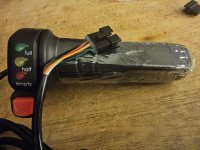
My hub kit originally came with a twist throttle, it has an on/off button and a three color led charge indicator. It came with a 6 pin connector color coded black, red, white, yellow, brown, green, in that order. (Btw, shouldn't it be only 5 wires for those functions, I thought 6 wires were for one extra function like low/high gear or a horn?)
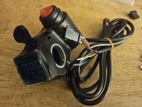
My replacement thumb throttle also has an on/off switch, and it has a 3 digits LED voltage screen. It has 5 wires, originally black, red, green in a 3 pin, then a blue female bullet connector and a yellow male bullet connector. I've changed the blue and yellow to a pin connector and I just need to assemble the pins back in a 6 pin connector (5 out of 6, one left empty)
How should I match my black, red, green, blue, yellow thumb throttle wires to my black, red, white, yellow, brown, green controller?
Please see included pics.
UPDATE:
Amberwolf, thanks a lot for all the help, I think I'm nearly there.
I found a way to insert the voltmeter probes while the old twist throttle is connected.
While it is connected:
When the twist throttle is on the OFF position: red, white, brown, green have 0V, yellow has 52V.
When the twist throttle is on the ON position: red has 4.3V, white has 0.8V, yellow, brown and green all have 52V.
It seems clear that red is the 5v positive, white is the throttle signal, and yellow sends the voltage to the thottle voltage led display. After that both brown and green seem to send back 52v to the controller to tell it that the throttle is ON, but I am clueless on which of the two (brown and green) my new throttle's blue wire is supposed to connect to. And also, is it safe to have the other one of the two have nothing connected to them? (after all my new throttle has 5 wires instead of the old one's 6).
Does anyone know which of the two I should connect my blue to, and if it's safe to have the other wire have nothing connected to it?
Attachments
Last edited:
") )
)