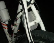
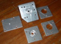
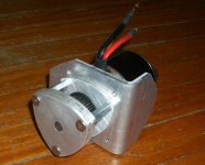
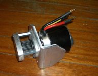
The Grinhill Mk2 RC-motor drive

Grinhill

10 kW
Joined
Jan 22, 2009
Messages
555
Location
Newcastle, Australia
As many on this forum will agree, it's never too early to start your next build. For those that aren't familiar with my first RC build, check out the link in my signature below.

Not an entire bike, this will be an evolutionary development, using the same bike. Unbolt one, bolt on the next. It will be able to use the same electrics, they can be upgraded separately. It's basically a combination of a few ideas I've had since finishing my first RC project.

I'll still try to meet the same starting specification as the Grinhill Mk1:
Here's my quick specs:
- weight less than 4kg (8 pounds) including batteries
- power in the range of 600W to 1200W
- bolt on with no mods to the frame, no mods to cranks, no mods to hubs
It will weigh a little more, and will accommodate a larger motor so it will be slighly more powerful (say, 1500W if electrics upgraded).

What do I like in my first build? The simple belt drive system. The lightweight battery. The easy-to-disassemble design. The low overall weight. The ability to freewheel.

What don't I like in my first build? The ESC losing sync. Being worried that the one-way bearing will fail. The mounting could be improved a little, a bit more stealth and more refined. Maybe a little more power wouldn't hurt.

What started this process? Two main things:
1. Wanting to mount the system within the frame triangle.
2. Wanting to use a larger one-way bearing.

Looking at the first point, when I did a mockup in my first design a location inside the triangle was my first choice, but it wouldn't be able to use the V-brake posts as they are on the wrong side to allow this. It's important to have a strong, flat plate to mount the system to. Here's a sketch incorporating a few ideas:
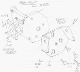
motormount27052009.jpg
 
Looking at point 2 - Without going to a two-stage design, I tried to find a larger bearing to fit within the pulley. Gets very messy.

Let's try a slightly larger motor, which has a lower Kv, so my overall ratio can change by a proportionate amount. So, let's look at 20-tooth pulleys. Still messy.

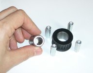
New idea - a separate jackshaft driven co-axially by the motor with some form of shaft coupling. Can now use a 1/2" shaft. For some reason, the bearings are half the price of metric ones (supply & demand?). And the beautiful thing is, there is a 20-tooth pulley with a 3/4" hub (to suit Shaftloc system) which will precisely fit the oneway bearing. No drilling required! Only available to suit 15mm wide belt, but that's OK.

Here's a comparison of the specs for my existing one-way bearing and the proposed one:
8mm ID 12mm OD 22mm wide, 4 Nm max torque - price AU$47
1/2" ID 3/4" OD 22mm wide, 8 Nm max torque - price AU$39
bike may09 004s.jpg

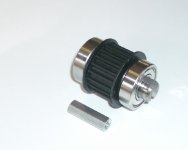
As I mentioned in my first build, I found a 2 inch long hardened 1/2" shaft in my garage so I already been tinkering. With this arrangement, the motor bearings will have no lateral load from the belt, since that is taken by the 1/2" shaft bearings. The motor bearings will be much happier since this is more like what they are designed for, e.g. turning a prop.

bike may09 007s.jpg

Shaft coupling - I want to keep it as compact as possible, so how about a slotted system (this is how distributor shafts were driven in older car engines.
Can I mount the jackshaft and the motor on a single thick aluminium angle bracket? This would mean a single attachment and adjustment point for the drive assembly.

The other support bearing could be mounted on some posts.
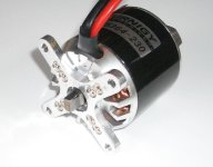
The motor could be mounted on some short posts, or even the X-shaped aluminium piece supplied with the motor. Note that using the X-piece would be quick, but would be bad from a motor cooling viewpoint.

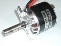
So, after attacking my motor and jackshaft with an angle grinder (I probably wouldn't do this to an Astro :) ):
rc_proj 033s.jpgrc_proj 038s.jpg
 
I'm following this one closely! I was inspired by your first creation, and will probably build something similar soon.

Please keep us posted, we appreciate following your reports.

Dave
 
Sorry for the hiatus on this one, a combination of flu, busy week at work, and a week's holiday with the family were the main factors.

On with the Bracket assembly - firstly a trip to the local sheetmetal shop. The company I work for deals regularly with them, so they supplied the aluminium for free and cut & folded the rough shapes as well. Unfortunately they only had 5mm thickness available, so I will have to double up to do the bearing supports.

The support bracket to be mounted to the frame took a bit of shaping with files and a hammer. It's held by three screws.

rc_proj 042s.jpg

Now for some manual cutting, shaping, trimming, filing, drilling etc for the motor bracket. I used a holesaw for the 1-1/8" holes for the bearings. I filed the holesaw teeth slightly so it was undersized rather than over. Since I don't have the right size reamer, I used a socket with some emery paper wrapped around the outside to get a snug fit for the bearings. (This method is not recommended, but it worked for me.)

rc_proj 041s.jpg

Note with two of the pieces I didn't bore all the way through since the bearings are only 8mm wide. I cleaned this up using a router.
 
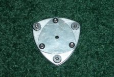
I've also done some further shaping on the bearing supports, again using my router and a jig I made up. I like the way the triangle shape parts turned out. I guess these parts could have been whipped up on a CNC machine in no time at all, but I find doing it the long way to be quite therapeutic.

rc_proj 044s.jpg

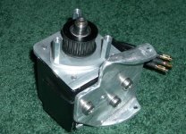
It's starting to look the part when assembled. I've done a trial fit just holding it in place on the bike, and it ends up nicely positioned.

rc_proj 045s.jpg
 
I'm liking the router machining!!

As a woodworker, I've got more routers than mills....

Carbide bits do wonders on Aluminum.

Template based machining is like poor mans CNC.

The bent bracket is also cool.
I bought square/rectangular alloy tubing, but with access to a press brake, you can save some dough for sure.

looking good Grinhill!
 
Sometimes in our automated world we forget that everything used to be made by hand. Heck, entire engines have been made with basic tools.

I like it!

Oh, you only need one of the 5mm plates as far as strength goes. Plus, if you use flanged bearings, you do not need a bottomed out hole.

So, any ETA on the maiden voyage?

Matt
 
Thanks for the support and tips guys.

If I get a chance for a session in the garage over the weekend I will be able to get it mounted up.

One more think to do is to finish mounting the motor. I have ended up with an 8mm gap from the motor face to the bracket, and I need to reduce this to 5mm so I can use another piece of aluminium (same mounting holes as the X-piece). This will allow removal of the motor without moving the pulley.

The easiest way to fix this is by shortening the jackshaft by 3mm on the outer end (I don't want to mess with the coupling, as it fits so well now and was very fiddly to get right).

I'm also thinking it would be nice to use a smaller diameter bearing as a thrust bearing for the end of the shaft, to prevent the coupling from being sloppy.
 
I like the shape of the outer bearing plate. It looks like the rotor in a wankle, or rotary engine.

FM
 
Grinhill, you give hope to the many aluminum "hackers" out there, like myself. I'll have to look into one of these new-fangled router thingys. :roll: :mrgreen:

Seriously beautiful work.

-- Gary
 
Joepostal said:
Can you take a picture of your Jig and router setup?
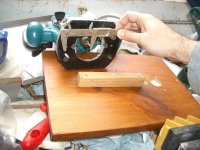
The trick with this shape is that the mounting holes are also the centres for machining. The 3 holes are 5mm with centres at 48mm. So the arc for trimming was about 55mm. Since this is quite small for a large router, I used the router's removable plastic baseplate as part of my jig.

In this photo you can see the extra M5 screw coming out of the router baseplate, this becomes the pivot point, to be inserted in the workpiece. I've also shown the underside of my wooden support piece, with a brace for attaching in the vice.

rc_proj 047s.jpg

Here's the setup in the vice. The workpiece is secured in the hollowed-out section by two screws, and the router's new pivot screw gets inserted in the vacant hole. Route away! :D

 
dnmun said:
with the 'distributor' cog drive, how do align the 2 shafts so they are coaxial? how tight is the fork over the cog?

The theory here is that both shafts are fixed in place, so the alignment will only be as good as I can get the centres aligned with my mounting system. I guess there will be a slight runout, I hope it won't cause too many problems. I'll just put a dab of grease on there and allow it to wobble a bit.

There's no play to speak of, but it's not an interference fit. The jackshaft slides over until it hits the rounded shoulders of the motor shaft.
 
I love how you have used the router :D
This has given me so many new idea's.
Great work.
Alex
 
Yeah so damn nice to see someone who has owned a router for a few years! Thanks for teaching us some new tricks.
I never owned a router it looks like a great tool for small machining. I do own a drillpress now FINALLY :)
 
Prompted by a failure of my first drive, it's time to get this one going.

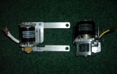
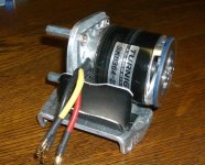
I swapped my heatsink over to the new drive, added some heat transfer past, tightened everything up, checked alignment of shaft. It was a bit out, had to bash the angle bracket with a hammer. Here's a side-by-side comparison with the first drive:
rc_proj 067s.jpg

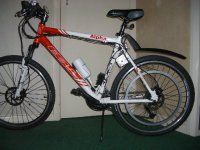
Now here's the finished bike:
rc_proj 061s.jpg

Time for a test ride. :D
Fantastic!!! So much smoother and quieter than the first one. The motor revs a bit slower for the same speed, because of the lower Kv.

Went well up the first hill, then I lost drive. :( The jackshaft slipped outboard and disengaged. I had used Loctite 262 (stud lock) which I had lying around to secure shaft to bearing, obviously not suitable for this application. Will use epoxy now. Will also buy a thrust bearing and fit to the end of the jackshaft.
 
I'm liking these builds - perfect for Aus - no officer, look at the size of the motor - how could it possibly produce more than 200W being that small?

Even though I got a cyclone kit, the tinkerer in me wants to try this design - probably design my own ESC, complete with regen - the throttle would be better as a twist hall effect - I do seem to remember that there is a circuit designed by branco justic(?) of oatley electronics that uses a hall throttle to produce servo pulses. I'll have a look, but it wouldn't be that hard to make anyway.

Just found it - not quite what we are after here though... http://www.siliconchip.com.au/cms/A_108753/article.html

What is the cogging effect like on these motors with no freewheel? Liveable or bad?

AH FUDGE - Fetcher has already designed one! http://endless-sphere.com/forums/viewtopic.php?f=16&t=9940

No sense in reinventing the wheel!
 
Heath
A few people have suggested they will do a similar build without the freewheel, I haven't seen any yet.

The cogging is not as noticeable with the larger motor, and the lower gear ratio also assists with this. Probably not much of an issue unless you are really into pedalling unassisted.

Design your own controller? Many others have talked about or attempted this (I wouldn't :mrgreen: ). Did you see this thread?
http://endless-sphere.com/forums/viewtopic.php?f=2&t=11246

The RC ESCs have a settable option for regen braking, but I assume you are talking about battery recharging. Adding 10% extra battery capacity is an easier way to go in my book. :)
 
What's with the slew of people that want to design their own controller? I thought that required geniuses or something. :mrgreen:

(*whoops, I forgot, there's a few of those on the board.)
 
Yeah regen braking was the ultimate idea - but I do like the lightweight approach taken here - its a lot more practical than lead acid and a bug hub motor, thats for sure! Doesn't exactly scream look at me either... especially if you had a rack + panniers to hide a lot of it.
 
OK, so the epoxy only lasted one test ride. The thrust bearing turned up (10mm x 4mm) so I had to do a bit more work to fit this:
View attachment 2
rc_proj 072s.jpg
Also had to fit a cover over the end to hold it out of 3mm aluminium, and routed a 1mm recess to hold bearing.
rc_proj 074s.jpg

After it was all reassembled, seems to work nicely.

Remember, this mucking around is all because I wanted to use the hardened 1/2" shaft I already had. The ultimate way to do this would be a single-piece 1/2" shaft with part of it turned down to 10mm to replace the motor shaft. (Although I have seen a few people have had trouble with disassembly of these motors).
 
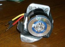
Here's a bit of bling I added last week as well - a motor end cover to form an impeller.
rc_proj 071s.jpg
Yes that is an old CD-R :D . I like to use recycled bits wherever possible.

I also needed a 2mm spacer with a 30mm hole. I found a piece of 2mm blue acrylic in my plastics junk box (originally from a radio dial, 70s vintage). I spun up the motor and used some sandpaper to clean it up, unfortunately scratched the can a bit as well :(
rc_proj 070s.jpg

I have said before that I don't think the fan helps with cooling as much as conductive heatsinking.
 
Back
Top