dontsendbubbamail
10 kW
- Joined
- May 28, 2008
- Messages
- 718
etard said:Wye are you building a new drive? :wink:
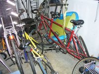
More details please, host bike, controller, batteries, belts, gears, etc....
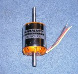
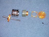
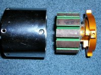
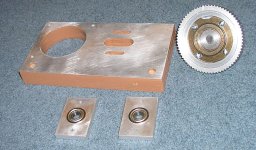
dontsendbubbamail said:It's a start. The body of the motor and the shaft are roughly an inch longer then the old style motor.
Bubba
dontsendbubbamail said:My other advice is don't ever lug the motor when going up a hill if you are using an RC controller. It only takes seconds for it to overheat and blow.
Bubba
")
recumpence said:Hey Bubba,
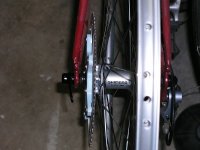
I have a disc brake to 130bcd adaptor I can donate. The normal adaptor I sell has 1/2 inch offset to the right. But, one test adaptor I have here is (I think) 3/8 offset. It is CNC machined aluminum anodized black. I will ship it to you if you would like.
Matt
You mean "Making an oily mess and ending up with multiple invisible splinters" is fun.dontsendbubbamail said:recumpence said:Hey Bubba,
I have a disc brake to 130bcd adaptor I can donate. The normal adaptor I sell has 1/2 inch offset to the right. But, one test adaptor I have here is (I think) 3/8 offset. It is CNC machined aluminum anodized black. I will ship it to you if you would like.
Matt
Making aluminum dust is fun.
Bubba
mud2005 said:Hey deguinox, you can get those from electricscooterparts.com. Eugene rules!
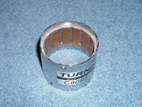
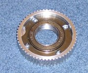
You're from 'round heya too? We should meet up sometime ...I'd love to see that build you're working on up close dontsendbubbamail said:The freewheel came from Tncscooters.com and cost a whole $7USD. Quality is about a low as it gets. This is not an item that will handle high power and hard accelerations.
Bubba