You are using an out of date browser. It may not display this or other websites correctly.
You should upgrade or use an alternative browser.
You should upgrade or use an alternative browser.
Active pre-charge/inrush control
- Thread starter boo
- Start date
dnmun
1 PW
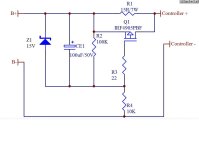
what is the 4905? will it handle the current?
you could just use a resistor to precharge the caps, then make the connection.
i recommended wiring up the input caps and mosfets on the main large red wire permanently, if the battery does not have to be removed. and put the circuit current on a switch.
but i have found out that some controllers have drain down resistors on the input caps so they bleed current all the time. i think it was alan b who discovered this.
so you would need to measure the leakage when the input caps are connected to see if your controller has that problem. he actually unsoldered the drain down resistor to prevent the pack from bleeding down through that resistor.
i don't remember which controller this is the problem for. the older inifineon controllers did not have that problem.
Jeremy Harris
100 MW
It's a good idea, but the choice of P channel FET isn't at all good, as it has a 20 mohm Rdson. This means that the FET will be dissipating 2 W at 10 A, 8 W at 20 A and 18 W at 30 A, so will need heat sinking, as it will run pretty hot.
Your are better to switch on the low side, as N channel FETs typically have a much lower Rdson. For example, the 75 V, 120 A, IRFB3077 has an Rdson of 3.6 mohm max, reducing the above losses by a factor of more than 5.
If you take a look at the way I switched the power with a soft start on my RFID ebike switch, here: http://endless-sphere.com/forums/viewtopic.php?f=2&t=39589&hilit=RFID#p578778 you can see that I used a bank of parallel IRFB4110 FETs, not to get better current handling, but just to reduce the Rdson and so get low losses. My ebike runs at up to 30 A through those 4 FETs and they barely get warm, as the total power dissipation is only about 1 W at 30 A, or about 0.25 W per FET.
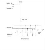
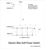
You could use the same switch circuit as I have, just connect a switch in series with the gate resistor to the FETs. I've drawn a quick and dirty circuit diagram to show how this works, below. The capacitor across the 10k resistor does the soft start, by turning the FET on (and off) slowly enough to avoid any appreciable surge current.

a PMOS, should handle the current but may run hot as Jeremy pointed out. i will do that, thanksdnmun said:what is the 4905? will it handle the current?
you could just use a resistor to precharge the caps, then make the connection.
i'd love to use RFID in the future. for now i will settle down on FETSJeremy Harris said:If you take a look at the way I switched the power with a soft start on my RFID ebike switch, here: viewtopic.php?f=2&t=39589&hilit=RFID#p578778 you can see that I used a bank of parallel IRFB4110 FETs, not to get better current handling, but just to reduce the Rdson and so get low losses. My ebike runs at up to 30 A through those 4 FETs and they barely get warm, as the total power dissipation is only about 1 W at 30 A, or about 0.25 W per FET.
This is more efficient circuit and I don't need to use a power switch. I can use a simple switch that can be mounted on the handle bar. ThanksJeremy Harris said:You could use the same switch circuit as I have, just connect a switch in series with the gate resistor to the FETs. I've drawn a quick and dirty circuit diagram to show how this works, below. The capacitor across the 10k resistor does the soft start, by turning the FET on (and off) slowly enough to avoid any appreciable surge current.
Gregory
100 kW
Hi,
I had a play around and made the Jeremy Harris FET based inrush protection switch.
It took me a whole day but I was stoked when it worked.
First time I’ve made a PCB since I was 15yo.
The bike is 15s lipo that peaks at 30A 1600W.
I made mine flat, soldering the FETs to the PCB trace. I used 3 x IRFB4110’s and they don’t get warm (on my short trips which are limited by the 5Ah pack on this bike, must try it with a bigger Ah).
I notched the powerpole housings so they sat flat.
Connectors are mirrored so you can’t really plug battery into controller socket on the board.
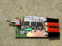
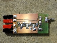
And a minor change was made to put a set of charge plugs next to the switch to make recharging much easier. And this is the final product.
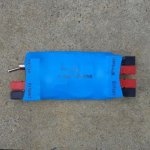
And it slid into the small tool bag on my bike.
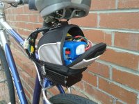
In hindsight I should have gotten a finer pen for the etch resist. Next plan is to learn to use one of the software packaged like KiCAD.
I might relocate the switch.
And if doing another one I would place the powerpole housings on top of the PCB rather than in line with it.
Thanks for the schematic Jeremy.
Greg
I had a play around and made the Jeremy Harris FET based inrush protection switch.
It took me a whole day but I was stoked when it worked.
First time I’ve made a PCB since I was 15yo.
The bike is 15s lipo that peaks at 30A 1600W.
I made mine flat, soldering the FETs to the PCB trace. I used 3 x IRFB4110’s and they don’t get warm (on my short trips which are limited by the 5Ah pack on this bike, must try it with a bigger Ah).
I notched the powerpole housings so they sat flat.
Connectors are mirrored so you can’t really plug battery into controller socket on the board.


And a minor change was made to put a set of charge plugs next to the switch to make recharging much easier. And this is the final product.

And it slid into the small tool bag on my bike.

In hindsight I should have gotten a finer pen for the etch resist. Next plan is to learn to use one of the software packaged like KiCAD.
I might relocate the switch.
And if doing another one I would place the powerpole housings on top of the PCB rather than in line with it.
Thanks for the schematic Jeremy.
Greg
Jeremy Harris
100 MW
Neat job, Greg.
I don't know why controllers don't have something like this integrated into them it would make life a lot easier if they did.
I don't know why controllers don't have something like this integrated into them it would make life a lot easier if they did.
Jeremy Harris
100 MW
Confab said:Does a precharge circuit only prevent the sparking or does it actually prevent current inrush damage?
The risk of damage is really only to the switch or connectors, rather than anything else. This can be quite severe on a big controller, I've had an Anderson get ruined in just a few connections from the spark.
Diamondback
10 kW
Hi all.
any chance that someone here would be interested in building one of these (either switched or RFID) for a fee ?
i would love to have one on my trike, but i truly suck at these kinds of projects.
i would love to have an RFID switch with the soft start feature....
id happily pay just about any reasonable fee.
the trike is 20A 12S2P lipo. (20A constant, around 35A peaks)
Jason.
Jeremy Harris
100 MW
I regret to say that I don't really have the time to put things like this together for people, much as it would be nice to be able to do it. I seem to have a workshop full of unfinished projects, with me flitting from one to another without getting enough time to complete many of them!
I'd suggest adding a 12v zener diode from gate to source on the FETs just to reduce the chances of blowing them up if the voltage is out of range. With a zener, both resistors could be something like 1M, and you could run anywhere from 24v to over 100v with the same components.
Some kind of heat sink on the FETs would be a good idea at higher current levels. I generally rate the 4110s at 20 amps each with minimal heat sinking.
Some kind of heat sink on the FETs would be a good idea at higher current levels. I generally rate the 4110s at 20 amps each with minimal heat sinking.
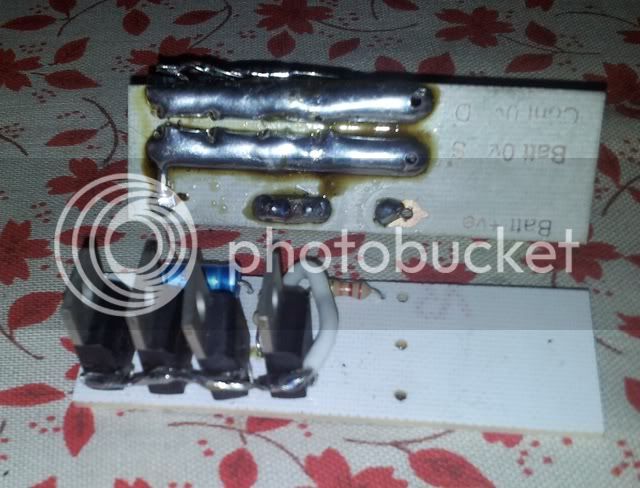
I've built a spare one you can have. It's got counterfeit IRB4110s, but the other two that I built with the same ones work perfectly and don't even get warm at 20 amps.Diamondback said:Hi all.
any chance that someone here would be interested in building one of these (either switched or RFID) for a fee ?
i would love to have one on my trike, but i truly suck at these kinds of projects.
i would love to have an RFID switch with the soft start feature....
id happily pay just about any reasonable fee.
the trike is 20A 12S2P lipo. (20A constant, around 35A peaks)
Jason.
It looks like this one and you have to solder on the switch, which I mounted remotely, and the battery wires.£7 plus cost of postage:
Diamondback
10 kW
sounds like a deal to me !
thanks.
PM on the way !
Jason.
thanks.
PM on the way !
Jason.
Jeremy Harris
100 MW
fechter said:I'd suggest adding a 12v zener diode from gate to source on the FETs just to reduce the chances of blowing them up if the voltage is out of range. With a zener, both resistors could be something like 1M, and you could run anywhere from 24v to over 100v with the same components.
Some kind of heat sink on the FETs would be a good idea at higher current levels. I generally rate the 4110s at 20 amps each with minimal heat sinking.
Being a minimalist, I just used resistor selection as the way to limit the gate voltage to a safe level, but you're right, clamping it with a zener would remove the need to fit the right value resistor.
I've found that 4 off 4110's don't even get luke warm at 30A controller current limit, which isn't surprising as the voltage drop across them is only about 34 mV or so at 30A, so each FET is only dissipating about 0.25 watt. Even at 60 A the FETs are only going to be dissipating about 1 W each, not enough to warrant a heatsink really. As it stands I think this switch should be OK for maybe 80 to 100 A without adding heatsinks, although I think I'd just add a couple of extra FETs to keep the losses down if I ever wanted to switch currents as high as that.
Jeremy Harris said:Being a minimalist, I just used resistor selection as the way to limit the gate voltage to a safe level, but you're right, clamping it with a zener would remove the need to fit the right value resistor.
We think alike. :wink:
The cost of a zener from Mouser is about $.05ea. About the same cost as a resistor.
It should also be possible to tie in the LVC from a cell level monitoring system like Methods' or CellLogs to kill the power in the event a cell goes low if this is desired. Personally, I like to just pull the throttle line down, but in the case of forgetting to turn off the power for a long time, it would cut power to the controller and draw only about 1uA per volt of battery voltage.
Jeremy Harris
100 MW
fechter said:We think alike. :wink:
The cost of a zener from Mouser is about $.05ea. About the same cost as a resistor.
Different countries, different prices! We seem to pay more for everything over here......................
fechter said:It should also be possible to tie in the LVC from a cell level monitoring system like Methods' or CellLogs to kill the power in the event a cell goes low if this is desired. Personally, I like to just pull the throttle line down, but in the case of forgetting to turn off the power for a long time, it would cut power to the controller and draw only about 1uA per volt of battery voltage.
Sure, but this was just a dirt simple switch, that emulates a mechanical switch, but without the spark. It could be a heck of a lot more complex and sophisticated, but I threw that circuit together in about a minute simply to fix the primary problem with the original design in the first post, the high on resistance of the P channel FET. It's just the power end of the switch in the RFID switch on my bike.
Diamondback
10 kW
Should R1 still be 22k for 12S lipo ? That's just over 50V fresh off the charger.
Jason.
Jason.
humm looking at the datasheet. Max current is 180A @10V but max power dissipation is 370W So if we have 4, wouldn't that theoretically limit you to 370*4 = 1480W?
But if use the 120A @10V, then we have theoretical max dissipation is 1200W per FET? so 4 is 4800W?
I am a bit confused on the Specs in the data sheet
But if use the 120A @10V, then we have theoretical max dissipation is 1200W per FET? so 4 is 4800W?
I am a bit confused on the Specs in the data sheet
shinyballs
1 kW
Wow, awesome contribution from Jeremy and Fechter's improvements! This should be standard equipment for every ebike.
To use the switch for higher voltages up to 150v, is IRFB4115 a good choice? and by replacing the 2 resistors to 1m, and a zener on each fet, it can be used for a much wider voltage range, right?
Regarding using the switch on a Kelly controller, they stated that to avoid damaging the controller, the Battery -V has to be connected 1st before applying power. On your diagram, can the power wires be reversed, meaning the gate connection comes from the Battery's -V, and fet source from Battery +V ?
Jeremy Harris
100 MW
Diamondback said:Should R1 still be 22k for 12S lipo ? That's just over 50V fresh off the charger.
Jason.
Yes, it would be OK. The maximum gate voltage allowed is 20V,and the gate needs at least about 8 to 10V to ensure the FETs are hard on, so the different resistor values were just my simple way to gate the drive voltage in the right range for each battery voltage.
In fact, at 50.4 V (for 12S LiCoO2 LiPo hot off charge) 22k is fine, as it gives a gate voltage of 15.75V. 33k for R1 would give a gate voltage of 11.72 V, which is also fine.
Jeremy Harris
100 MW
mvly said:humm looking at the datasheet. Max current is 180A @10V but max power dissipation is 370W So if we have 4, wouldn't that theoretically limit you to 370*4 = 1480W?
But if use the 120A @10V, then we have theoretical max dissipation is 1200W per FET? so 4 is 4800W?
I am a bit confused on the Specs in the data sheet
You can pretty much ignore the FET power dissipation in the datasheet, as it's misleading and can rarely ever be achieved, because the FET can't get rid of heat through any real heatsink at a rate that would allow that dissipation figure to be reached.
The key here is to look at the FET dissipation relative to the power being handled. For example, at 30 A and 50 V this switch will be carrying 1.5 kW. However, the FETs have an on resistance of about 4.5 mohms each, and there are four of them in parallel, so the total on resistance is 1/4 of this, about 1.125 mohms, or 0.00125 ohms.
The power lost across the FET switch is given by I²R, where I is the current and R is the total FET on resistance. For 30 A, I²R = 30² x 0.00125 = 1.125 W. This will be shared by all four FETs, so each will be dissipating about 0.281 W when the switch is handling 1500 W.
If the voltage was increased to 80 V, and the current kept at 30 A, then the FET dissipation would stay the same as above, but the switch would then be handling 2400 W.
Upping the current to 60 A increases the FET dissipation by a factor of four (because of the I² factor), so each FET would be then dissipating about 1.125 W. This is still fine without a heatsink, but if going much higher then I'd be inclined to add more FETs in parallel, to reduce the on resistance and losses further.
Jeremy Harris
100 MW
shinyballs said:Wow, awesome contribution from Jeremy and Fechter's improvements! This should be standard equipment for every ebike.
To use the switch for higher voltages up to 150v, is IRFB4115 a good choice? and by replacing the 2 resistors to 1m, and a zener on each fet, it can be used for a much wider voltage range, right?
Regarding using the switch on a Kelly controller, they stated that to avoid damaging the controller, the Battery -V has to be connected 1st before applying power. On your diagram, can the power wires be reversed, meaning the gate connection comes from the Battery's -V, and fet source from Battery +V ?
Don't increase the resistors to 1M, it's far too high a value to get a zener to turn on reliably (they need around 1 mA to get to the start of the turn on knee) and it would also increase the FET turn on/off time to a point where the FETs might well start to complain. The range of turn on times (and turn off times) I selected was intended to keep the FETs in the safe area, even when using a controller with a lot of capacitance (like the big Kelly's).
By all means add a 12V zener across the 10k resistor but then keep the value of R1 at 22k. This would be fine for any voltage from around 36 V (where the zener current would be about 1 mA) to 90 V (where the zener current would be about 3.5 mA). At 90V R1 would need to be at least a 1/2 W rated part, below 80 V a 1/4 W resistor for R1 is fine.
Sure, you can use 4115s for higher voltages, but I'd suggest changing R1 to 56k for voltages above 100 V and using a 12 V zener across the 10k resistor. Use a 1/2 W resistor for R1. You will need more 4115s to get the same on resistance (and hence low losses) as the 4110 version, as they have a higher Rdson. I'd suggest using at least 8 of them if you want to switch up to 60A, perhaps more, as the 4115 has around 2.4 times higher losses than the 4110.
You can't reverse the connections, this switch has to be in the low side. This shouldn't be a problem for the Kelly, as long as all of the low side (-ve) connections are to the switched low side, i.e. the FET drain connections.
shinyballs
1 kW
Thank you for the very thorough explanation. Based on your input, do you mind if I show the changes I made to your Soft Power switch diagram for your perusal?
Jeremy Harris
100 MW
shinyballs said:Thank you for the very thorough explanation. Based on your input, do you mind if I show the changes I made to your Soft Power switch diagram for your perusal?
Fire away, anything I put on here is just open source doodling, for anyone to use or mod as they see fit.
shinyballs
1 kW
Regarding my battery pack which is in a series/parallel switch arrangement - i.e. 32s or 16s2p LiFePO4 (106V or 53V) to power the controller. Can I tap on cell#16 +V and use a 33k gate resistor?
So, either if the battery pack is switched in series or parallel, the gate voltage doesn't change.
So, either if the battery pack is switched in series or parallel, the gate voltage doesn't change.
Attachments
Similar threads
- Replies
- 4
- Views
- 358
- Replies
- 25
- Views
- 941
- Replies
- 5
- Views
- 1,359
- Replies
- 5
- Views
- 1,171


