i ended up buying 4 genuine fets from another ES member who did a bulk order.
my next question is.....
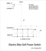
is anyone able (or willing) to create a PCB mask (for Jeremy's original design) that i might be able to have etched ?
or better still, make a PCB for me (ill happily pay for the time and parts + postage fees)
i have downloaded eagle free PCB maker, but it's over my head im afraid.
im sure if i have a proper PCB, i can build this. im not so confident in using prototyping / vero board for this.
i have all of the required components to build this, with the exception of the PCB.
the enclosure i have bought is 8x5x3cm external.
@ Jeremy
if i mount the whole thing in a small electronics enclosure, will the fets get hot ? (given my application of 20A cont)
also, im going to add a fuse on the positive line, just before the circuit.
it strikes me as strange that the vast majority of ebikes / conversions i see, are running no fuse.
i intend to add plugs on either side of the circuit so the switch can be removed from the trike should it ever fail in the middle of nowhere.
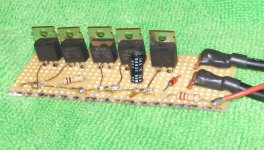
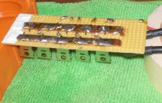
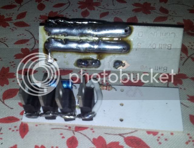
here's where im at with it at the moment...


Jason.


")