Minimally invasive 9C temp probe surgery

Beachcruzer

100 W
Joined
Jul 30, 2011
Messages
210
Location
Dana Point, California
*Edit* I took John in CR's suggestion to wire a temp probe through the right side axle. Scroll down for the play-by-play.

I always wondered how doctors could start a tonsillectomy and end up removing somebody's spleen. Now I think I get it.

I opened up my 9C to install a temp probe, and discovered all the wires are potted into the axle with epoxy. I don't want to replace my phases just yet, and really don't want to mess with the Halls. Has anybody developed a minimally invasive technique to run the temp probe wires through the axel without taking a chisel to that gob of epoxy?
 
The ones I've seen so far seem to be a soft black silicone, rather than epoxy, and it's usually only at the elbow on the stator end, where the wires exit the axle inside the motor. If so, you might be able to simply pierce that with a stiff larger gauge wire, poking all the way thru till you get it to the outside end of the axle.

Then solder your probe wires to one end of the larger wire, and pull it thru with that.
 
Two good options and a reality check. Great responses guys, thanks. I'm going to stare at it for a couple hours, maybe try Amberwolf's plan first and if I can't make that work I'll either fall back to John's option or just end up ripping everything out and doing the LFP phase mod. To be continued . . .
 
Okay, so I tried Amberwolf's suggestion and it seemed like it was going to work. I pulled out the silicone at the base of the axel and pushed a clotheshanger through from the outside. I got enough depth, but couldn't get it to turn the corner. After half a dozen tries, I switched to 14 gauge house wire. That seemed even more promising, but still couldn't get it through the right-angle transition at the base of the axle.

1.jpg

The point of this exercise is to avoid replacing the phase and Hall wires, and after a while I started thinking that potentially jamming a sharp object through the insulation on said wires is not such a good idea. I went and got the knock-off Dremel tool. Plan B was John in CR's idea: just cut a channel in the other side of the axel and bring the temp probe wires out that way.

2.jpg

The cut took 10 minutes at most. Easy. It's about 1 mm wide and 2 mm deep. I had to curve the channel because the fake Dremel is too big to get the cut-off wheel perpendicular at the base of the axel.

3.jpg

We don't have Canadian Tire down here (no Ben Horton's either) so I couldn't copy Doctorbass's method completely. I used the first $10 barbecue thermometer I found at Lowes. I chose this one because it has a small display and internal battery. The guts of them all seem to be the same, with a tiny sensor that fits easily under the windings.
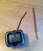
5.jpg

The hardest part of this whole exercise was stripping back the insulation on the tiny wires that lead to the probe. I spliced them to some 22 or so gauge wire I scavenged from a computer cord. Dab of solder, some shrink and we're good to go.

7.jpg

I placed the probe under the windings near the magnet, exactly where El Steak put his in this useful thread about temp probe options: http://endless-sphere.com/forums/viewtopic.php?f=1&t=25502 It's a little hard to spot, in the 12 O'Clock position in the pic.

4.jpg

I secured the wires in the axle slot with a little 420 epoxy leftover from my Doc Bass torque arm installation. The wires exit on the flat of the axle and through the open part of the dropouts. I didn't have to cut the wire to install the wheel; it's a continuous line straight to the handlebar.

View attachment 1

This particular cheapo thermometer has a pivoting head feature, which would be totally useless if it didn't provide a perfect spot to slip a couple of zip ties through. It makes for a clean and secure bar mount.
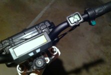
9.jpg
 
I'm glad it worked for you Beachcruzer. Now I'm more inclined to do some temperature sensing myself. Most of my motors are such that getting the left side cover off means reworking the motor harness, but the right side is easy to pop right off.
John
 
awesome job! surprised i've not seen this technique before.
Beachcruzer said:
The hardest part of this whole exercise was stripping back the insulation on the tiny wires that lead to the probe. I spliced them to some 22 or so gauge wire I scavenged from a computer cord. Dab of solder, some shrink and we're good to go.
i'm not sure how much power you're running, or if the computer wires are inside the motor or outside, but for high power setups, it's a good idea to use high temp wire inside the motor, so the insulation doesn't melt. the insulation is also very thin and slippery which makes such tasks a lot easier. 10/12g is great for phase wire upgrades and 24g is great for hall wires. outside the motor you can use whatever, but put lots of heatshink around the soldered splice job. if it's ever exposed to water and especially moves back and forth it will get rather brittle and break at the solder point...
 
GCinDC said:
awesome job! surprised i've not seen this technique before.
Beachcruzer said:
The hardest part of this whole exercise was stripping back the insulation on the tiny wires that lead to the probe. I spliced them to some 22 or so gauge wire I scavenged from a computer cord. Dab of solder, some shrink and we're good to go.
i'm not sure how much power you're running, or if the computer wires are inside the motor or outside, but for high power setups, it's a good idea to use high temp wire inside the motor, so the insulation doesn't melt. the insulation is also very thin and slippery which makes such tasks a lot easier. 10/12g is great for phase wire upgrades and 24g is great for hall wires. outside the motor you can use whatever, but put lots of heatshink around the soldered splice job. if it's ever exposed to water and especially moves back and forth it will get rather brittle and break at the solder point...

Doh! The computer wires are inside the motor. One consequence of using the shorter "stick the meat once" BBQ probe (as opposed to the longer "stick it and forget it" probes that Doctorbass pioneered) is that I had to run the extension wire to within about three inches of the actual temp sensor. That wire has a single layer of shrink around it. So, I guess we'll see how long this installation lasts.

One reason I decided to run the wires out this side of the motor is ease of replacement. The Amazon reviews for all of the BBQ sensors I looked at basically said "worked great for x days or months, then quit." So I'm thinking there's a good chance I'm going to have to replace this sensor at some point. With this set up I can do that just by pulling the right cover. I don't have to re-thread anything through the axle or even remove the stator.

If/when I need to do that replacement, I'll get a replacement probe with a longer wire that is designed to go in the oven or BBQ, and use that wire exclusively inside the motor. That should improve the heat resistance.

Power levels are TBD. Right now I'm running 24s lipo at 100 volts hot and a 40 amp controller. I saw 3,800 watts on the CA on a short test ride, and the temperature rose pretty quickly to 100 C. I'll be dialing that back to a sustainable level with the help of this temp sensor. My guess is I'll settle at about 25 amps, and ride at 1,500 watts or less sustained. This is on the 2810 9C, a slow-wind motor that goes just over 32 mph at 100 volts, and climbs like a mountain goat.
 
If it goes past the thermal limit of heat shrink, you'll have much bigger problems than your sensor wires. Assuming it's 2, the only issue is if their insulation melts and they short with each other.
 
Back
Top