Field Oriented Control using dsPic33

Burtie

10 kW
Joined
Mar 27, 2009
Messages
543
Location
UK
Field oriented control (or vector control) of brushless motors promises many advantages over the simpler 6 step trapezoidal control.
Here are a few advantages that spring to mind;

1) Because the force is always kept at 90deg to the rotor, it should be more efficient.
2) For the same reason it should also generate less audible noise.
3) The use of space vector modulation, means it should be better able to drive low inductance loads.
4) The use of fast phase current monitoring means it should be better able to protect the power stage.
5) The algorithm allows accurate +/- torque control, allowing variable regenerative braking


The disadvantages ??
1) The algorithm requires a lot of computational power
2) It takes me ages to get my head around how it works :?
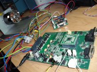
FOController.jpg


There are a handful of development kits around for this sort of work, from companies like Ti, ST, NXP, Toshiba, many of them based on ARM 32bit processors.
Atmel also have a kit based on their AVR32.

Microchip offer their motor development platform based on their range of digital signal processors dsPIC30 and dsPIC33.
Although only 16 bits, these devices run fast, have a specialised instruction set and compiler for doing this kind of job, and contain hardware specialy designed to deal with motor control.


I chose the Microchip dsPIC33, since it seemed about the cheapest way for me to get up and going, there is a whole raft of application notes and example code to start you off, and captain Lebowski appears to be having great success with a similar device !


Most of the Microchip examples are aimed at reducing the parts count to a minimum when driving things like washing machines and air conditioner fans. Where starting torque and slow speed operation is not so important. The FOC examples are all sensorless and required careful tailoring of hard coded parameters to work with each different motor I tried.
The sensorless position estimating needed to know the inductance and resistance values of each motor, so the motor behaviour could be modeled (or predicted).

This is all well and good, if you are making 100,000 washing machines -all the same, but no good for the 1-off ebike here and there :(

Consequently I found some adaptation was necessary:
I removed the open-loop sensorless startup, and the sensorless position estimation , and replace it all with our familiar 3 hall sensors and a bit of code to run a timer which interpolates the rotors angle between the sensors.

It works a treat. Nice dependable high torque startup, smooth slow running, and no need to know the values of the motor phase inductance or resistance :)

http://www.youtube.com/watch?v=YFREKbPm5Gw&feature=youtu.be
[youtube]YFREKbPm5Gw[/youtube]
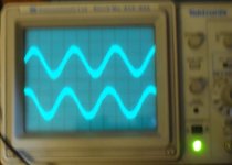

Phase Waveforms.jpg

Next step, will be to build a bigger power stage so I can run the C80-100 motor on my RC dyno.

EDIT: Now done, can be seen in this thread here:
http://endless-sphere.com/forums/viewtopic.php?f=30&t=44910&start=100#p694066


Burtie
 
Burtie you rock!

Thanks for the post. After years of study at the ES school of higher education, I actually understood most of that. Thank you, and all the other ES big brains out there, for sharing your thoughts on this forum.
 
Looks very promising, I'm guessing this will work with your optical boards too?

Keep up the good work, I've a huge eMax scooter motor that this might be perfect for
 
Do you run some sort of PLL or DLL to interpolate between the hall signals, and use this to provide
sine waves to the motor. Do you compensate for the delay due to motor inductances ?
 
I am running the standard Microchip AN1078 FOC algorithm, except the rotor angle is supplied by a digital delay-locked loop synced to the hall sensors.
Any delay due to motor inductance should be compensated for by the FOC algorithm.

There is also scope for applying timing advance via the dll, to achieve field weakening, and raise the kv (all be it at the expense of some efficiency).

The motor I am using happens to have a very sinusoidal BEMF signature, so the drive voltages also look very sinusoidal.

Burtie
 
Burtie said:
The motor I am using happens to have a very sinusoidal BEMF signature, so the drive voltages also look very sinusoidal.
Burtie

AFAIK there no relation between the drive waveform and the back-emf waveform ? FOC cares about the fundamentals, thats it.
 
I imagined that when only pushing small phase currents at low speed (as is the case here, --unloaded motor), the drive voltage would closely match the BEMF.

As the speed and current increase, stator inductance and resistance will become more significant in the equation, and cause the drive waveform shape to change.
 
Burtie said:
I imagined that when only pushing small phase currents at low speed (as is the case here, --unloaded motor), the drive voltage would closely match the BEMF.

As the speed and current increase, stator inductance and resistance will become more significant in the equation, and cause the drive waveform shape to change.

Hm, are you sure ? The way I see it the controller outputs a sine wave to matter what the back-emf waveform is. At no load, with a
back emf not equal to a sine, there will be some discrepancy resulting in the motor accellerating / decellerating at a high
rate. This causes the typical 'electric motor whine'. Since most motors make close to a sine wave back emf they are
quiet when fed with a sine. When the amplitude increases and the controller starts clipping its output sine the whine returns.
 
Very cool burtie. Can't wait to see where you go with this.
 
Subscribed. 8)

Many thanks, KF
 
Think I might be getting into deep water here ..... :wink:


Lebowski said:
Hm, are you sure ? ...

I think so.

given:
R is phase resistance
L is phase inductance
I is phase current

At any given time the driving voltage, V, across 1 phase of the motor, will be:

V = Vbemf + I*R + L* dI/dt

so if I is kept small, then: V =(approx) Vbemf


Consider the more general case---
If the motor is running in steady state (i.e. velocity is constant, torque is constant) The FOC will attempt to keep Iq and Id constant.

To achieve this, Ia, Ib, Ic must be varying sinusoidally, 120 degrees apart. (These are the phase currents that are measured by the FOC system).

The system will attempt to vary the voltage applied to each phase in any way necessary to achieve this. Note this voltage is not necessarily sinusoidal, but depends on the inductance, resistance, BEMF characteristic, speed and torque of the motor, as described in the equation above.


If saturation occurs, and the ideal voltage can no longer be applied, we get torque ripple (because Iq and Id are no longer constant). And this will generate a higher level of audiable noise


Sound plausable ?
Burtie
 
Ehm, looking at the system in AN1078, the waveform to the motor is determined/ calculated in the Inverse Park and inverse Clark transformation block ( figure 10 and 11). Because the inverse Park uses sine functions you'll end up with sine waves at the output, the waveform shape has nothing to do with the back emf.... me thinks :D

Also in the Clark and Park transforms the implicit assumption is made that the waveforms are sinusoidal (In the Clarke by having vectors of equal length)
 
Err um :D
Would it be fair to say...

The inverse Park transform will only output pure sinusoid signals if its inputs, Vq and Vd, are constant.

Vq and Vd are the outputs from the two PI controllers, so these quantities will be constantly changing due to any miss-match between IqRef and IqMeasured or IdRef and IdMeasured.
Result - control voltages are not necessarily pure sinusoid.


If a FOC system was unable to modify the shape of its control voltages, it would have no advantage over the much simpler pure sine wave controller as described in AN1017 "Sinusoidal Control of PMSM Motors with dsPIC30F DSC"

Edit -- FOC system will compensate for inductance by correcting timing, Simpler sinusoidal drive will not.

The Clark and Park transforms deal with transforming current vectors, most of which we are aiming to make sinusoidal.
The Inverse Clark and Inverse Park transforms are dealing with voltage vectors, which we are controlling in order to try and create the sinusoidal currents.


Burtie
 
Burtie,
Nice work in modding the FOC code to work in sensored mode. I have the same microchip development board and had some limited success a while back in using it to drive a modest 6-FET power stage (2kW driving a 30 inch prop). I however was implementing microchips more basic trapezoidal commutation code (can't remember the apnote numbers) in both sensored and sensorless mode. I do remember that the low rpm control in sensorless mode was much better than any of the RC ESC's could offer while driving the C80100. I shelved my development following a power board melt down. Your success with FOC has got me thinking about picking it back up again and rebuilding the power stage. Thanks. :D
Martin

https://www.youtube.com/watch?v=8TMRn5TOvIA
https://www.youtube.com/watch?v=Rj0mz2glt7c
 
Burtie said:
Vq and Vd are the outputs from the two PI controllers, so these quantities will be constantly changing due to any miss-match between IqRef and IqMeasured or IdRef and IdMeasured.
Result - control voltages are not necessarily pure sinusoid.

True, but are the bandwidths of those two PI controllers not too low for this ? I would think the
bandwidths are too low to follow the voltages as it goes through 1 e-rpm, that the PI controll loops
controll the 'long term average' (long term being a few e-rpm cycles)
 
Lebowski said:
Ehm, looking at the system in AN1078, the waveform to the motor is determined/ calculated in the Inverse Park and inverse Clark transformation block ( figure 10 and 11). Because the inverse Park uses sine functions you'll end up with sine waves at the output, the waveform shape has nothing to do with the back emf.... me thinks :D

Also in the Clark and Park transforms the implicit assumption is made that the waveforms are sinusoidal (In the Clarke by having vectors of equal length)
Shouldn't the output wave form depend on what reference waveform that is used in the control? In the AN1078 case the code is for Space Vector Modulation (SVM) with a output waveform like this.
Phase voltage
https://dl.dropbox.com/u/53678622/665rpm-Vph.png
Line voltage
https://dl.dropbox.com/u/53678622/665rpm-Vll.png
Line voltage not sinusoidal, but rather triangular with rounded peaks.
 
Lebowski said:
Burtie said:
Vq and Vd are the outputs from the two PI controllers, so these quantities will be constantly changing due to any miss-match between IqRef and IqMeasured or IdRef and IdMeasured.
Result - control voltages are not necessarily pure sinusoid.

True, but are the bandwidths of those two PI controllers not too low for this ? I would think the
bandwidths are too low to follow the voltages as it goes through 1 e-rpm, that the PI controll loops
controll the 'long term average' (long term being a few e-rpm cycles)


Good question.
-I looked at the code, and it seems the PI loops for Vq and Vd are executed every pwm cycle (20khz), so the bandwidth is easily enough to modify the waveform within 1 electrical revolution.

The PI loop controlling the speed is the only one that runs slower than this, at 1kHz.
 
Mr.K said:
Shouldn't the output wave form depend on what reference waveform that is used in the control? In the AN1078 case the code is for Space Vector Modulation (SVM) with a output waveform like this.
Phase voltage
https://dl.dropbox.com/u/53678622/665rpm-Vph.png
Line voltage
https://dl.dropbox.com/u/53678622/665rpm-Vll.png
Line voltage not sinusoidal, but rather triangular with rounded peaks.

Yes the waveform will appear differently depending how you look at it. In the scope picture I posted earlier, the (isolated)scope probe was connected across two phase wires, and shows a trace similar to the second image you posted.

Connecting the probe between one phase wire and Ground will yield a trace similar to the first image you posted.
 
mauimart said:
Burtie,
Nice work in modding the FOC code to work in sensored mode. I have the same microchip development board and had some limited success a while back in using it to drive a modest 6-FET power stage (2kW driving a 30 inch prop). I however was implementing microchips more basic trapezoidal commutation code (can't remember the apnote numbers) in both sensored and sensorless mode. I do remember that the low rpm control in sensorless mode was much better than any of the RC ESC's could offer while driving the C80100. I shelved my development following a power board melt down. Your success with FOC has got me thinking about picking it back up again and rebuilding the power stage. Thanks. :D
Martin

https://www.youtube.com/watch?v=8TMRn5TOvIA
https://www.youtube.com/watch?v=Rj0mz2glt7c


Nice work Martin, you need to dig out that board and patch it up to get the show back on the road !
I can hep you with the code for the AN1078 sensored conversion If you like. I will PM you soon.

Burtie
 
Mr.K said:
Lebowski said:
Ehm, looking at the system in AN1078, the waveform to the motor is determined/ calculated in the Inverse Park and inverse Clark transformation block ( figure 10 and 11). Because the inverse Park uses sine functions you'll end up with sine waves at the output, the waveform shape has nothing to do with the back emf.... me thinks :D

Also in the Clark and Park transforms the implicit assumption is made that the waveforms are sinusoidal (In the Clarke by having vectors of equal length)
Shouldn't the output wave form depend on what reference waveform that is used in the control? In the AN1078 case the code is for Space Vector Modulation (SVM) with a output waveform like this.
Phase voltage
https://dl.dropbox.com/u/53678622/665rpm-Vph.png
Line voltage
https://dl.dropbox.com/u/53678622/665rpm-Vll.png
Line voltage not sinusoidal, but rather triangular with rounded peaks.

It seems they're using a moving midpoint to get to a bit higher amplitude...
 
Burtie said:
Good question.
-I looked at the code, and it seems the PI loops for Vq and Vd are executed every pwm cycle (20khz), so the bandwidth is easily enough to modify the waveform within 1 electrical revolution.

The PI loop controlling the speed is the only one that runs slower than this, at 1kHz.

The bandwidth is not determined solely by the sample rate (20 kHz), but by samplerate and loop coefficients... pity I can't see the code here
 
Alan B said:
Very nice work!

After having done what you have, do you feel the extra speed of the ARM is worthwhile? Would it make the job easier or not?

Looking at my controller etc, the capabilities of the ADC are most important, processor speed comes second. For me an ARM makes no
sence as I don't need the speed and it would need a separate ADC chip...
 
Lebowski said:
Alan B said:
Very nice work!

After having done what you have, do you feel the extra speed of the ARM is worthwhile? Would it make the job easier or not?

Looking at my controller etc, the capabilities of the ADC are most important, processor speed comes second. For me an ARM makes no
sence as I don't need the speed and it would need a separate ADC chip...

If the ADC is the most important item then perhaps a separate ADC is indicated. ADCs in micro chips are hardly the epitome of ADC performance!
 
Back
Top