DIY BLDC/PMAC Innerrnner Motor using induction motor core.

Arlo1

1 TW
Joined
Apr 26, 2009
Messages
8,460
Location
Nanaimo
Ok so.... I have talked about it. Now its time to talk more and get a design down. I will most likely need to learn LTsplice more then I have and FEMM for this all to come together. But as most of you have seen IM building my own controllers and aiming for the sky for POWER. There is more then one way to skin a cat.

But lets start off with the reasons I want to chase this carrot.
1 Cost. I'm not rich and if you think about it the biggest reason for electric vehicles is saving money.
2 I LOVE DIY
3 I want more power then you can normally find in a store bought Motor.
4 This is for a car ( the next step) and if the Honda CRX makes decent power I will build a bigger one for the Road Runner.
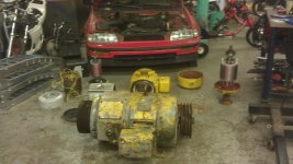
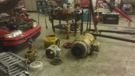
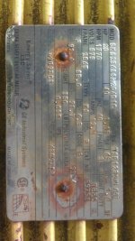
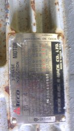
5 Induction motors are cheep and some times free. I have 5 two are little 1/2 and 1 hp single phase motors 2 are 10hp (continuous rated) 215t frame and
1 is a 256t 20 hp (continuous rated) motor.

Ok so here is my basic plan.
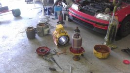
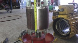
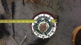
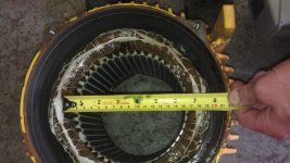
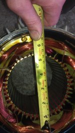
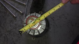
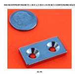
I will take one of the 215t frame motors and make a magnet filled rotor for it with permanent magnets Neo mags? I will get it running and see what kind of power I can make.
If that goes well I will move on to making a bigger one. IN the meantime I will make an aluminum casing to help with cooling weight and size. As well I will look at an oil cooling system the feeds oil into the housing and sprays it on the ends of the rotor and the rotor will centrifugally spray it on the end turns on the windings. This will help keep the magnets and the windings cool.
 

Attachments

  • 607.jpg
    607.jpg
    63.3 KB · Views: 4,250
  • 609.jpg
    609.jpg
    57.4 KB · Views: 4,250
  • 610.jpg
    610.jpg
    58.3 KB · Views: 4,250
  • 611.jpg
    611.jpg
    64.9 KB · Views: 4,250
  • 678.jpg
    678.jpg
    59.3 KB · Views: 4,250
  • 632.jpg
    632.jpg
    63.9 KB · Views: 4,250
  • 625.jpg
    625.jpg
    71.1 KB · Views: 4,250
  • 630.jpg
    630.jpg
    44.1 KB · Views: 4,250
Now the rotor would most likely be simple to build maybe just a pipe machined with flats for the roes of magnets.
And some of these magnets? but with a higher temp rating I think these are 80 deg. 150 deg would be more appropriate from what I have read and been shown. I think with 2 screws with lock tight and lock tight hysol on the magnet to steal surface.... I would like to make a fancy rotor but its got to be easy to make. I also thought about just mounting mags on the old rotor but the lams inside an induction rotor are skewed and I'm not sure how well that would work for back iron.
 

Attachments

  • Capture.JPG
    Capture.JPG
    35.1 KB · Views: 4,261
Im open to suggestions and links for magnets and aluminum tubing for the casing (need 8.25 id)
 
I'm not sure about the effect of using countersunk screws like that, as a fixing......

This is a handy site for relative values/strengths etc. https://www.hkcm.de/hkcm.php?osCsid=afb387bf39ebc5d14de799c908ed39d0&Design=Design&dna=3&des=on&mA=30&mB=5&mH=3

48t stator?
 
Maybe it's possible to make a "solid slot" winding. Since the stator is so big, it will probably generate enough EMF with only that one turn per slot.

Should start with a static analysis in FEMM, to get a feel for how good the magnetic path is with permanent magnet. The reason this hasn't already been done may be because of the iron design, alloy, and lamination thickness.
 
circuit said:
You will have to rewind it, you know?
Why not just rewind it for higher Kv and use with AC controller?
I don't follow you. These are induction motors they realy don't have a KV....
 
bearing said:
Maybe it's possible to make a "solid slot" winding. Since the stator is so big, it will probably generate enough EMF with only that one turn per slot.

Should start with a static analysis in FEMM, to get a feel for how good the magnetic path is with permanent magnet. The reason this hasn't already been done may be because of the iron design, alloy, and lamination thickness.
I think the lam thickness is ok. I will measure today. And one of the mods form DIY electric car lives a couple hours away and he has a motor that is permanent magnets inside and looks just like a converted induction motor. I think the reason this isn't done much is cause of the cost of an controller. But 100kw+ in a controller is something I wan to tackle anyway.

Yes I was realy thinking solid slot will be possible. Which means an easy machined strip of copper or aluminum for each slot then machined end pieces to connect them. I would love to build a solid slot motor.

Only problem is if the KV is to low I will need to run uber high amps and this becomes a controller nightmare. I would say 1000 amps is the highest I would dream of going before upping the voltage. I have been looking for mosfet modules with hi amp rating and they are hard to find.

Yes I will need to start learning fem. It is best to get this right before spending/wasting money on it.
 
I think you will make a better end result using the OEM induction motor rotor. :)
Rewind it with many less turns and setup cooling right on it and drive it HARD.
If you stay induction, when you just want to be cruising along at light throttle you will have much lower core losses.
 
liveforphysics said:
I think you will make a better end result using the OEM induction motor rotor. :)
Rewind it with many less turns and setup cooling right on it and drive it HARD.
If you stay induction, when you just want to be cruising along at light throttle you will have much lower core losses.
Thanks man. I have a few of them so I would like to make at least one a PMAC motor.
 
Arlo1 said:
circuit said:
You will have to rewind it, you know?
Why not just rewind it for higher Kv and use with AC controller?
I don't follow you. These are induction motors they realy don't have a KV....
Actually, they do. To get higher power from induction motor, you have to increase rpm. To increase rpm, you have to drive it with higher voltage and frequency, just like with bldc motor. And you can lower required voltage by rewinding the stator.
When you insert magnets in the rotor, flux will increase dramatically and you will need even more voltage to drive it with so many windings. So you will have to rewind it anyway.
 
circuit said:
Arlo1 said:
circuit said:
You will have to rewind it, you know?
Why not just rewind it for higher Kv and use with AC controller?
I don't follow you. These are induction motors they realy don't have a KV....
Actually, they do. To get higher power from induction motor, you have to increase rpm. To increase rpm, you have to drive it with higher voltage and frequency, just like with bldc motor. And you can lower required voltage by rewinding the stator.
When you insert magnets in the rotor, flux will increase dramatically and you will need even more voltage to drive it with so many windings. So you will have to rewind it anyway.
The frequency of the controller determines the rpm when unloaded. If you want to have power to higher rpm you need more voltage or less turns...

I do plan to rewind these motors but I want to get a baseline kv first if possible.
 
OK so I managed to use the winding calculator and got a perfact winding factor of 1 for each! .... Its designed for out runners but will give some food for thought.
 

Attachments

  • 36 slot 1.JPG
    36 slot 1.JPG
    80.6 KB · Views: 4,064
  • 48 slot 1.JPG
    48 slot 1.JPG
    87.8 KB · Views: 4,064
Winding factor of 1 probably doesn't work though, because it means the magnets are just aligned with the teeth. It will have only 36 heavy cogging steps per turn. If you change the number of magnets to a good number, you can get several hundred cogging steps per turn, which means it will turn smoother when you turn it by hand.

On a coreless motor, it probably works just fine, though.
 
No winding factor of 1 is the best you can get. We don't care what it feels like to spin by hand. Chances are I will wind it in WYE so it will not feel much for resistance when un powered anyway.
 
Are you sure?
Then I don't understand why more motors are wound that way.

EDIT:
I found an answer
To have a fundamental winding factor of 1, N:p = 3:1, using distributed winding. Design of stators for distributed windings and concentrated windings are also different, since distributed winded coils, the magnet line flow to only one direction, while concentrated winded coils, the flow is bi-directional. That is why for distributed windings, the outer ring of the stator need to be thicker.
http://www.rcgroups.com/forums/showthread.php?t=1788281#post23521768

So it needs less iron between each pole with the LRK winding and similar (concentrated), thus gets lighter. But since this stator most likely had distributed windings from the beginning, it already has got that extra iron.
 
That's not a motor.... THIS is a motor :)
 

Attachments

  • 068 (800 x 450).jpg
    068 (800 x 450).jpg
    57.4 KB · Views: 3,931
  • 069 (800 x 450).jpg
    069 (800 x 450).jpg
    57.3 KB · Views: 3,931
man I wish I had your garage setup :D I'm just working on a single table in my spare bedroom...

If you do this conversion, do you need a laminated rotor ? I mean, with the magnets on the rotor it's a bit
like the rotor becomes what in a RC motor is the can. And the flux ring in the can of an RC motor is never laminated...
This because it doesn't see a changing magnetic field (the field changes, or rotates, but the rotor follows this
so w.r.t. the rotor the field is stationary)

instead of screwing the magnets to the rotor you can also glue them and then wind a single filament of carbon fibre around it ?

By the way, when you make your rotor, inserting it will be violent and you probably need a car jack to get it out again so watch out !

That big one will turn your car into a pretzel ! :D
 
Lebowski said:
man I wish I had your garage setup :D I'm just working on a single table in my spare bedroom...
Yup Im very lucky to have my shop... Its for sale maybe come buy it?
lebowski said:
If you do this conversion, do you need a laminated rotor ? I mean, with the magnets on the rotor it's a bit
like the rotor becomes what in a RC motor is the can. And the flux ring in the can of an RC motor is never laminated...
That's why I started this thread its to figure out an easy way to make a good rotor.
What I have gathered is you can use laminated rotors with magnets held in place to allow for higher rpm but it looks like you will lose some torque.
lebowski said:
Instead of screwing the magnets to the rotor you can also glue them and then wind a single filament of carbon fibre around it ?
Yeah I have been thinking about that.... Remember the rotor will expand and contract with heat so what ever I use for resin and composite materials needs to be able to be run at 100-200 deg C with out loosing strength and not crack when stretched.
I have Kevlar and Carbon fiber. I have epoxy resin and hi temp polyester resin.....
lebowski said:
By the way, when you make your rotor, inserting it will be violent and you probably need a car jack to get it out again so watch out !
Thanks I have been thinking about this I think I will need to design a jig for removal and install.....
In Honda school one of our instructors warned us about the new (at that time) generators with rare earth mags that have sliced a few of their finger tips off lol.
lebowski said:
That big one will turn your car into a pretzel ! :D
No the big one will be for my 1969 Road Runner if this goes well. The motor in it now has ~600 ft/lbs and 550 Hp I have been planning to add frame connectors to the car which I need if I get better tires with the ICE motor anyway.
and Im still limited to what ever I can build for a controller.....;)
 
Ok So I took the big one apart. Its a wound rotor which means I have Laminations for a out runner and an inner runner.

So here is the numbers maybe you guys can help me make an educated guess on continuous torque (or max) I can make with oil cooling the windings (or without)

1 is a 215t frame with a 36 tooth stator. It has a 6" long stator and 5.5 inches dia. with .020" thick lams
2 is a 215t frame with a 48 tooth stator. It has a 5.75" long stator with 5.5 inches dia. with .020 thick lams
3 is a 256 frame with a 36 tooth stator. It has 6" long stator with 7"dia with .020 thick lams
4 is the big one... its a 364z frame with 60 tooth stator and IN this motor the stator is 5.125" long and 10.25" dia. this one will make some serious torque.
5 is if I used the rotor from 4 and made an out runner. I think it would be the same for torque density.

I don't know what magnets I will use but If anyone has links to magnet supplies for 150 deg C and decent pull force or N rating let me know.
Im guessing N42 magnets. I think they are the strongest I found to 150 deg c temp
 
Arlo1 said:
I don't know what magnets I will use but If anyone has links to magnet supplies for 150 deg C and decent pull force or N rating let me know.
Im guessing N42 magnets. I think they are the strongest I found to 150 deg c temp
It's better value to get slightly larger N35 magnets.
 
Lebowski said:
http://www.supermagnete.ch/eng/
I can't find any with counter sink holes?
 
Back
Top