DIY Toroidal Axial Flux PM

BalorNG said:
What's phase to phase resistance of your motor, for instance (or single phase resistance, which is half of it)?

I actually forgot I had a spreadsheet where I calculated it given the phase length and the properties of the wire
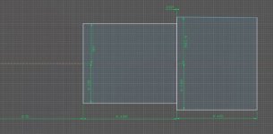
Screenshot 2022-08-23 233009.png

So if that's accurate, ~0.156 Ohm
 
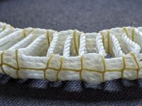
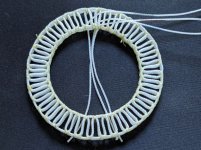
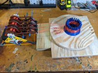
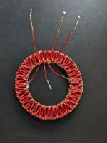
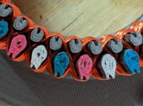
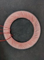
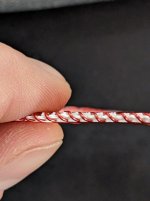
I finished the new nylon winding using the new winding machine contraption, I also tied it down with the kevlar. This time I tied it down twice at each overlap hopping to keep the shape of everything better as I tightened it up. I think it came out much better. and I am curious how this will work with the copper now. The nylon has some springy-ness (technichal term), and obviously it stays together better than my untwisted stranded wire.

Heres an example of a previous nylon winding I made. This one I attempted to insert plastic cores into the slots, so it might have gotten a little distressed from that, but it never looked as good as the other
PXL_20220825_122403630 small.jpg

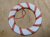
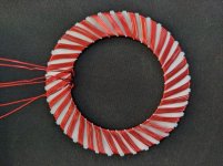
And the newest one
PXL_20220825_122352671 small.jpg


I also focused on the beginning an ending more to ensure that things were as orderly as possible given how I'm winding it. I think it looks pretty good. Copper is next!
PXL_20220825_122437838 small.jpg
 
Beautiful, that's looking really tight and professional. :thumb:
Super nice machine... Bring on the copper!
 
APL said:
Beautiful, that's looking really tight and professional. :thumb:
Super nice machine... Bring on the copper!
Thanks!

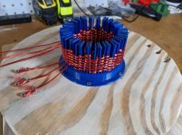
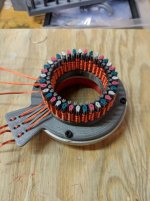
Finished winding the next stator, but I still need to tie it down. The machine definitely helped, but working with the copper was different from the string and I had expected. having everything stay tighter, and in once place while I wound it was a huge advantage. I think it only took me about 45 minutes to wind the whole thing, and I think the next one could be quicker now that I know its quirks.

One issue I noticed is that the fins bunched up into groups of three. I am hoping this is less of an issue once I tie it down, but I might need to change the winder slightly to have thicker fins, hopefully to prevent them from bending so easily. Carbon find would be nice too.... I could see making them with forged carbon fiber, or something, but would it really be worth the effort??

6 turns on this one, just like the last one. tying it is time consuming ill get to that soon. another benefit of the winding machine is I can leave it wound but untied without worrying about it getting loose or coming undone
PXL_20220827_120737133 small.jpg
PXL_20220827_120719920.MP small.jpg
 
While winding it went great, tying it down was a huge pain. The find that had pulled in close together made it very difficult to get the thread where it needed to be and it was all so tight that it kept breaking the kevlar thread. I could potentially get thicker thread, but I think the real issue is what ever is causing the fins to bunch up. I believe it from simply pulling things too tight. I might just use another fin or something similar to hold them apart while I pull things tight.

Either way, it looks pretty good. It took a very long time to get it fully tied down. I ended up winding around the outside diameter. and then actually popped it off the jig to wind the inside diameter, but I needed to be very careful to prevent the loops from combining/separating. I actually re-did the outer diameter once I had the center done because of how loose it all was.

PXL_20220830_112020120 small.jpg


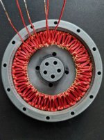
It fits nicely in the mold, and has much longer phase wires than the last one, which I intend to keep long so I can play with star vs delta for real this time.

PXL_20220830_112104668 small.jpg


Next step is to pot it. I never did fix the seal on my pressure pot....
 
Soooo I still have yet to fix the pressure pot. But I was able to make some progress in others ways.

A while back someone reached out to me after my last YouTube video. They ended up making a part for me but due to the 3D printer optimized design, it was not right when it was made out of aluminum, but I had a local machinist fix it recently, and I was actually able to use it. this helped resolve one of the issues I was having with trueness, and irregularities from the printed parts.

With this I attempted to test the torque on a load cell. but it just bounced off over and over, and I was unable to get a good reading of the force.

I then tried to make a Prony brake. This seemed to work a bit better, and I was able to get ~450g of force at a distance of 50mm from the center of the shaft. This seems like the first sort of concrete number that I have gotten for torque.

450g @ 50mm = 22.5gram*meters or 0.220Nm
The power supply pulled just about 4A @ 12V

So please correct me if I am wrong, but I believe this puts the Kt at about 0.055Nm/A
I think this puts it on par with some other brushless motors, but at about half the weight
https://endless-sphere.com/forums/viewtopic.php?t=45489

Maybe I am mis-interpreting the results. I would love to get some feedback.

The load cell was calibrated before the test, but I'm sure theres a margin of error in there. Also the Prony brake did not work entirely as intended. I dont think it was really slipping when I got the reading so the RPM was quite low.

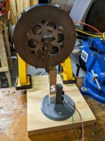
You'll also notice that I threaded the shaft, So maybe now I can hook a prop up to it and see what kind of load I can put on it.
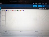
PXL_20221026_211941261-small.jpg
PXL_20221026_232357213-small.jpg

Sorry for the low quality pictures. I just took a picture of my laptop with my phone at the time. and the other photo did not focus well because of the angle that it sits on the workshop bench.
 
HalbachHero said:
450g @ 50mm = 22.5gram*meters or 0.220Nm
The power supply pulled just about 4A @ 12V

So please correct me if I am wrong, but I believe this puts the Kt at about 0.055Nm/A
I think this puts it on par with some other brushless motors, but at about half the weight
https://endless-sphere.com/forums/viewtopic.php?t=45489

Maybe I am mis-interpreting the results. I would love to get some feedback.

Ehm. You most certianly are.

Power supply (or battery) draw does not equal phase current at static load, not by a *very* long shot.
What's you phase to phase resistance? You can calculate your actual amps from it and your battery current.
 
BalorNG said:
Power supply (or battery) draw does not equal phase current at static load, not by a *very* long shot.
What's you phase to phase resistance? You can calculate your actual amps from it and your battery current.

Thanks for the feedback.
Phase to phase resistance is not something I have been able to measure accurately. But based on the parameters of the conductor. I have calculated it at 0.31177 Ohms.

I'm not sure how to get current from that, but I would assume its just
V= I * R
12 = I * 0.31177
I = ~38.5A
Is that right? maybe my controller is limited? Or is that math wrong too? haha
 
HalbachHero said:
BalorNG said:
Power supply (or battery) draw does not equal phase current at static load, not by a *very* long shot.
What's you phase to phase resistance? You can calculate your actual amps from it and your battery current.

Thanks for the feedback.
Phase to phase resistance is not something I have been able to measure accurately. But based on the parameters of the conductor. I have calculated it at 0.31177 Ohms.

I'm not sure how to get current from that, but I would assume its just
V= I * R
12 = I * 0.31177
I = ~38.5A
Is that right? maybe my controller is limited? Or is that math wrong too? haha

Yup, sounds about right. Have you measured your KV? It should be in 1000+ range...
But than 8.3 torque conversion constant likely does not really work with coreless motors:
https://things-in-motion.blogspot.com/2018/12/how-to-estimate-torque-of-bldc-pmsm.html
 
Anyway, expecting coreless motor to have higher torque per amp than equivalent iron core motor is... overly optimistic :)
That's emphatically not their strong suit... lack of 'iron losses' is. I'd love to have one of those in a form of regen-braking (fixed gear) middrive that has minimal losses when off, but it would be much heavier/larger than a typical iron core motor or spin much faster.
 
BalorNG said:
Anyway, expecting coreless motor to have higher torque per amp than equivalent iron core motor is... overly optimistic :)
That's emphatically not their strong suit... lack of 'iron losses' is.

Thanks for the input :)
 
HalbachHero said:
With this I attempted to test the torque on a load cell. but it just bounced off over and over, and I was unable to get a good reading of the force.

I then tried to make a Prony brake. This seemed to work a bit better, and I was able to get ~450g of force at a distance of 50mm from the center of the shaft. This seems like the first sort of concrete number that I have gotten for torque.

Oh, missed that. Since your rotor is not fully stalled, it was producing work (4A were not *only* resistive losses).

You must multiply RPMs and torque and subtract that watts from batter current draw...

Oh yea, and you forgot that I^2 :)
 
BalorNG said:
Oh yea, and you forgot that I^2
So would this be a power equation? I used 12, which was voltage. But if it's power, would it be power from the power supply? Or something other value?

If it's from the power supply it's
12vx4A=48w
P=I^R
Then
48w=I^2 * 0.3117
I = ~12A

Am I missing something?
 
HalbachHero said:
BalorNG said:
Oh yea, and you forgot that I^2
So would this be a power equation? I used 12, which was voltage. But if it's power, would it be power from the power supply? Or something other value?

If it's from the power supply it's
12vx4A=48w
P=I^R
Then
48w=I^2 * 0.3117
I = ~12A

Am I missing something?

Basically, when your motor is not producing any *mechanical* work (only torque), only 'work' being produced, hence, is joule heating, with formula of I^2*R (that includes losses in controller and wires outside the motor though, that may add up).

Since you cannot measure your phase current directly, than you can safely calculate phase current from *power* drawn and your phase to phase resistance *provided*, again, that you subtract actual mechanical work produced from watts drawn, because your rotor was NOT stalled due to lack of halls.

Anyway, again, provided conversion coefficienct of 8.3 holds, (see article above, it's great), your KV should be around 400. Have you measured it?
Your no-load RPM should be around 5k... but that would depend on revs you've been measuring the torque at.
At 2k RPM torque of 0.23 Nm with 100% efficiency will require 48w by itself, barring perpetuum mobile shenanigans :)
 
So I have purchased a VESC (finally). Its the VESC 6 EDU from Trampa boards.

I got the VESC tool as well, and have started to wrap my head around it. I think I have a decent understanding of the basic FOC settings, but I am unable to get it to start sensorless. I have measured the Kv (Spun with a drill for 15 seconds, and took an average reading with my scope with the probe clipped to one wire, and the ground clipped to another. I measured 82.01Hz @ 2.44V to get ~176Kv) with my scope given the current configuration of the motor. And the resistance is based on a calculation of the proportions of the conductor, since I am struggling to measure it in another way. (155.8 mOhm)

I am not sure if I measured the Ld - Lq correctly. I tried 0, and I tried the difference between the induction between the two wire pairs. (11uH, and 10.9uH) I cannot tell if either made a real difference between tests.

I found that with a push start I can get it to run sensorless. So I calculated the Lambda
Lambda = (60/(sqrt(3) * 2 * pi() * Kv * Npp) ) * 1000 to get mWb
for me this calculated to 2.597 mWb
Then I played with the value to see if I could get it to run at start, or smoother or anything. I found that lowering the lambda value from my calculation reduced the average current at any given duty cycle. I was able to get it to run at a 10% duty cycle at ~150mA.

Oh also it was virtually silent, I actually couldn't even tell it was running, so that was kind of neat too.

I have seen Benjamin Vedder has posted some more videos about HFI, and am curious if thats something that would be useful. I would think not due to it being coreless, but I dont really know much about it.

These are the parameters that I used in my best attempt.
Screenshot from 2022-12-05 18-27-45.png
 
Yes, but the numbers that appear are pretty wacky when I do that. I have to imagine it has something to do with the bad resistance reading, but I'm not positive.
I have had the most success using calculated values and adjusting
 
If you enter your own values, you need to hit the "calc apply old" button. Just in case you had not realised.

HFI will probably be completely useless, but you never know. The magnets themselves/lack of magnet in the gaps might provide some salience.

I have some motors that work amazingly with HFI and others that are terrible. One thing that does help is low inductance, because that gives a bigger signal. You have low inductance!
 
mxlemming said:
If you enter your own values, you need to hit the "calc apply old" button. Just in case you had not realised.

Thanks, I have been using the "calc apply old" for my manually entered values.

I believe that I had incorrectly calculated my resistance values, but to no avail.

I have been playing with HFI, also with no luck yet.

Admittedly all the settings are a bit beyond me, I am slowly trying to learn them one at a time.


In the mean time, I have been in contact with some machinists to try to get some parts made for the next version. I have modified the design to accommodate a thicker stator, and I can now use spacers to get things into the right position between the rotors. I'm hoping this can serve as a platform to make a bunch of stators around. but its been a bit slow going lately
 
In paralell to testing the one working motor, I have been working on the next version. Even though I had already made a set of rotors that has yet to be used (due to not being able to get the center piece machined).

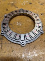
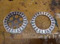
I found that there was actually quite a bit of space between the inner diameter of the magnet ring. I played with this a bit and got was able to shrink things a decent amount. From ~96mm to ~90mm. I realize that this might increase the Kv with the same number of windings, but I think bringing the magnets closer together is only a good thing, and obviously reducing the diameter impacts the total weight and inertia.
This image is the new on laying on top of the old one
PXL_20221217_210628089-small.jpg


Also this version of the rotors includes a change that I mentioned a bit ago, which is using the iron in the center as well, instead of needing to machine a large aluminum hub. Hopefully making it cheaper and easier to make. Also, the iron is 1.6mm, so although its denser than aluminum, I think the total weight will come out to about the same.
PXL_20221217_210527740-small.jpg


I also have been spending some time making a new type of stator winding. I made an overlapped serpentine winding that I would like to test. This is using the new smaller diameter. I made a separate winding jig, which I have already found some issues with it. Basically plastic is not going to be strong enough to wind one precisely all the way up. So I may change how the windings are made.
But this is where I'm at so far.
PXL_20221231_190419578-small.jpg
PXL_20221231_190356574-small.jpg
 
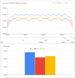
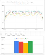
Lately I have been helping another maker with some simulations and found some information that might be obvious. But ideally the halbach array is tightly packed (minimize the gaps between poles, but also that the halbach magnets are the same width and height as the axial ones.
Heres the data
Screenshot 2023-03-01 175050.png

Screenshot 2023-03-01 175025.png


Using this information I decided to think about another rotor design (I know, another one). Also, a while back I recall reading that there was some optimization to be had with a ratio or OD:ID it was ~70% if I recall correctly, Anyway with that in mind, I was thinking about how you could get a halbach array the most tightly packed. Obviously segmenting and using various sizes would be ideal, but it might be difficult to procure specific size magnets. And cutting them can get into all sorts of issues.

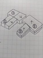
I found that there is a nice ratio of a length to width ratio of 6:7 with the magnets that allows you to use 2 kinds of magnets for a rotor, 1 magnet will work in 3 of the 4 positions needed
WhatsApp Image 2023-02-23 at 11.41.53.jpgWhatsApp Image 2023-02-23 at 11.40.16.jpgWhatsApp Image 2023-02-23 at 11.45.33.jpg


using 3mm x 3mm x 3.5mm magnets, You could get a maximum gap of 0.6mm between any one magnet. Hopefully reducing costs, while making an efficient rotor


Also, I was not able to nicely tie the serpentine winding off of the jig, so after a while I gave up.
In the mean time, I was working on making a Faulhaber winding jig, which so far is coming along nicely
PXL_20230301_224538459.jpg
 
The last attempt at the Faulhaber winding was just a test. After tweaking things a few times, I managed to make this. This is two 3d printed pieces that I glued together.
PXL_20230311_210712959.jpgPXL_20230311_210751614.jpg

There are three turns on each phase, still 12 poles. I decided to give up on the stranded wire. I switched to a 24 AWG (0.51mm). I think I want to try stacking them, or even layered windings. I think if I continue with the air core idea, I could pack more turns into a smaller thickness this way, possibly bringing the rotors closer together to keep the amount of copper down.
I was thinking I would still pot this and use sheets of fiberglass to keep it more rigid.

I also will try to make some stators the other way, using the solid wire too.
 
After a few more iterations. I landed on something I think I like. This is 3 phases, with 5 turns each and It's just a little under 2mm thick. I only added the "gear teeth" between each phase instead of each turn, and was able to get them to pile up next to each other nicely. Obviously I need to test this, but I like how easy this type is to wind. If it's rigid enough after potting. This might be worth it
I am thinking I will order this same part to be laser cut with carbon fiber 1mm thick. and still use fiberglass sheets to further stiffen it.PXL_20230315_215318615.jpg
 
...I am thinking I will order this same part to be laser cut with carbon fiber 1mm thick. and still use fiberglass sheets to further stiffen it.
It's not easy to bond new composites to already cured composites. You could cure the carbon with a peel ply or maybe find some with a surface finish ready for bonding.
You could look at using other core materials too. Balsa might work well (as long as it gets sealed.) It can also be easily laser cut.

You could also 3D print your winding ring with triangulated (or honeycomb) cutouts like a screen. You could then use that as the winding jig that then becomes a sandwich core for the composites. The holes in the ring allow the 2 sides to be connected and be much more rigid. There are different composite fillers you could use to fill those voids. This should reduce fdm print time a bunch too. The composite won't likely bond with the print but should be strong with the composite filled / connected voids.
You could also add these voids in a different core material like balsa mentioned above.

How does a 3mm X 3mm X 3mm cube magnet look in your setup? Really asking if it's worth going through the trouble for the extra .5mm for the other magnet while trying to build / glue it all up.
 
Last edited:
Back
Top