Here is a link to the now [strike]un[/strike]official user guide and other documents and thread index by Teklektik
http://www.endless-sphere.com/forums/viewtopic.php?p=571345#p571345
and the wiki
http://www.endless-sphere.com/w/index.php/Cycle_Analyst_v3_Setup
and the official CAv3 info page
http://www.ebikes.ca/product-info/grin-products/cycle-analyst-3.html
Here is a key post index graciously compiled by Teklektik to help people find things amongst the nearly 4000 posts on this thread - JLE
******************************** Back to original post that started this thread ************************************
Hey everyone, so I alluded back in the RC-CA thread last year that we'd basically hit the ceiling of what could be fit in that board layout and were working on a new model with more I/O functionality and software space. http://endless-sphere.com/forums/viewtopic.php?f=28&t=29846&start=145
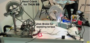
There've been a few kinks to work out and board revisions since then, but we had a good demo built in time for the Taipei bike show earlier this month. Here was our ghetto booth setup were you could turn the crank, look at your human power generation on the CA and watch either the hub motor or the RC motor spin up in response:
The back end of the circuitboard now looks like this, with the top row having all the new input/output headers:
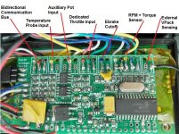
Communcation: There is an Rx / Tx and Gnd for hooking up a TTL->USB converter. This can be used for datalogging, plus bootloading new firmware, and configuring setup parameters from a computer rather than by pushing buttons through the setup menu.
Temperature:This input can be either a 10K NTC thermistor, or a linear temperature sensing IC like the LMx35 series. It has an onboard 1K pullup to 5V, so with a 10K thermistor you get good sensitivity in the 80-100 oC temperature range where it matters, and with the IC devices like the LM335 that act like a zener diode you don't need a separate 5V either, just the same 2pins.
Aux Pot Input: This is a general purpose 0-5V input that can be used either with a potentiometer or any number of 2/3/4 position switches with resistor dividers to scale any one of the limit parameters on the fly while biking.
Ebrake Cutoff: Brake inhibit input, has onboard pullup as well so you can use either a mechanical brake switch or a hall effect device. This way you don't need brake signal wires going all the way back to the controller, they can go into the CA and then the CA cuts the throttle signal.
RPM / Dir / Trq: The pedal assist connector was laid out primarily with the THUN torque sensing bottom brackets in mind, but will work fine with regular PAS cadence sensors, as well as the torque sensors we saw from two other companies at the Taipei show (FAG from germany and GreenTrans from taiwan). The 10V bus can power the THUN sensor directly provided you are using a pack that is 48V or less. For higher voltages the CA's regulator would get hot and you'd want to feed the THUN 12V power from a DC-DC. RPM is where the cadence pulses are measured, and the Dir input lets it distinguish between forwards and reverse pedal motion. So this works both with quadrature encoded signals like the THUN, or with regular PAS sensors that have pulses on one signal and a steady fwd/rev on another.
External VPack: Finally, the last input is for a separate battery voltage signal. For people running >100V, this gives the option of wiring up a resistive divider at your battery side for sensing the pack voltage and feeding just this signal to the CA, with the CA itself being powered from a lower 12V bus or similar. This is a much safer approach for higher voltage systems than powering the CA directly at those levels, and it means up to 650V packs could be supported.
One of the main objectives for all of this was so that we can consolidate all of the different ebike/human interface signals into the CA, have the CA act as a customizable brain for how these things should interact, and then provide a single command to the throttle input of any model of motor controller. That way litterally any existing ebike system could be upgraded for torque sensing PAS assist, over-temperature rollback etc. Like this:
http://www.endless-sphere.com/forums/viewtopic.php?p=571345#p571345
and the wiki
http://www.endless-sphere.com/w/index.php/Cycle_Analyst_v3_Setup
and the official CAv3 info page
http://www.ebikes.ca/product-info/grin-products/cycle-analyst-3.html
Here is a key post index graciously compiled by Teklektik to help people find things amongst the nearly 4000 posts on this thread - JLE
- Official Bug and Enhancement Lists
- Fixes
- Complete Procedure to re-flash firmware, restore factory default calibration and settings, and perform the CA Throttle setup, etc.
(Use only if EEPROM is corrupted.) - How to extract and post a Settings File
- Procedure to fix corrupt Calibration values (e.g. RShunt can't be edited, Voltage is incorrect, etc)
- Complete Procedure to re-flash firmware, restore factory default calibration and settings, and perform the CA Throttle setup, etc.
- Throttle + Gain Adjustments + Proportional Regen
- FastRamp and UpRamp Tuning
- Explanation of Diode/NoDiode ThrOut Connections for CA Models
- Parallelling two throttles (for separate proportional regen control)
- Throttle Bar Graph Flashes on Powerup
- Fix for slow throttle activation after initial power-up (Error in Guide section 5.2)
- Gain Adjustment to Remedy Speed Limiting Due to Rapid Acceleration
- Simple Magura Throttle Curve Shaper
- Proposal for AUX Pot Preset Switch
- Circumventing Controller 'Missing Throttle' Safety Circuit
- Tuning Techniques for Speed Throttle
- Interaction of Non-Limiting Gain Setup - Slow Throttle response - circa v3B19
- Alternating 'A/a' in Limiting Display with Current Throttle
- Hall Throttle Non-linearity Issues
- Open Loop/Closed Loop Functional Overview
- Summary of Throttle (Diode) Connections by PCB Revisions
- Details of CA v3 Throttle Connection
- Background on CA/Controller Throttle Connection
- Using Resistive (Magura) Throttles
- Avoiding Shutdown from Controller Input Fault Voltage
- 'Large Screen Compatible' CA-DP Interface Change - throttle Connection
- Cruise Control
- Auxiliary CTRL Function - Aux Pot
- Ebrake Notes
- PAS/Torque Sensor Notes
- Adjusting Torque Scaling vs PAS Assist
- PAS Tuning Tips & Techniques
- Adjustment Workaround for Thun/TDCM Surge When Resuming After Braking (3-0p6)
- Max Throttle PAS Speed
- Summary of Torque Sensor Products/Manufacturers
- DIY PAS Sensor
- Thun Torque sensor use and gain adjustment circa V3B19
- Torque Sensor Sampling Technique
- Thun Sensor BB Fit
- Battery Pack Voltage Limitations for THUN Sensor
- Using PAS as Mid-drive RPM Monitor 1
- Using PAS as Mid-drive RPM Monitor 2
- PAS Settings and Pickup Hints for Smoother Getaways
- Manufacturer Tools from Thun to Select the Proper Thun Sensor
- Using 12v Laptop Supply for Aux THUN Power
- Thun Config Trick for Hand Cycle
- Thermistor Notes
- About Temp Sensor Gnd Wire and Hall Connection
- Table of setting for common KTY linear parts
- Thoughts on motor temperatures and rollback ranges
- Procedure to Calibrate Linear Mode Devices
- Hooking up an older EM3EV V2 Controller and Motor w/Temp Sensor to a V3
- Capacitor fix for temp display jitter (thru B22)
- NTC Thermistors - proper beta constant
- Using Two Temperature Sensors
- LM35
- Workaround for v3B12 Lookup Table Error (Assumes Wrong Pull-up Resistor)
- Temperature Errors Due to Improper Ground Reference
- Connectors/Wiring/Power
- Wiring CA-DP red V+ to PCB 'ignition' pad
- Kelly Controller Hookup
- Fix, schematic, PCB layout for blown protection diode
- Clarification of Guide Current Limit Table (circa p6)
- FDTI Programming Cable
- Vbatt Power Plug for Accessories
- Discussion of Power Isolation for High Voltage Vehicles
- CA cable/connector pin out and color code
- 'Large Screen Compatible' Controller CA-DP Interface Change
- Shunt Notes
- Analogger
- Battery - SOC - VShutdown - LVC
- Bootloader + Serial Interface (PC COM port)
- Logging Data with a Phone or PC
- Using the CA Setting Utility 'CalOverwrite' Capability (Fix Corrupted EEPROM)
- Basic Bootloader Protocol for External EEPROM Access
- Additional Notes on Bootloader Use (circa v3B21)
- EEPROM Layout - Spreadsheet (circa v3B21)
- Bootloader How-To
- Notes about flashing and Setup parameters
- Plan for avoiding Setup parameter overwrite
- Coming Bootloader Features
- How to Bulk Load Setup Parms Using Bootloader
- About the Special Bootloader USB->RS-232 Cable
- Display Algorithms/Issues
- Misc Calibration and Settings
- Misc Bug/Fix Information
- Spontaneous Console Button Pushes - Electrical Noise
- Software Setup Utility 1.3 Freezes and Crashes CA
- No boot - dark display problem (no backlight)
- Fix, schematic, PCB layout for blown protection diode
- Correction to Guide 3-0p6i Shunt Calibration Procedure
- Adjustment Workaround for Thun/TDCM Surge When Resuming After Braking (3-0p6)
- Configuring 'Monitor Only' mode - all CA throttle control (limiting) is disabled
- Zero Amps to fix Stuck Gas Gauge
- Procedure to fix corrupt Calibration values (e.g. RShunt can't be edited)
- Fix for slow throttle activation after initial power-up (Error in Guide section 5.2)
- Spurious WOT on Controller Power-up circa V3B19
- V3B19_NoCal Calibration Parameter Overwrite
- V3B19_NoCal Non-Calibration Parameter Overwrite
- Spurious Human Power Readings circa v3B19
- Rev 2 PCB - Varying Voltage Readings - Add Capacitor Fix
- Known Bugs circa v3B17
- Workaround for pre-v3B16 400+mph Speedometer Readings (Speed Limit cutouts, etc)
******************************** Back to original post that started this thread ************************************
Hey everyone, so I alluded back in the RC-CA thread last year that we'd basically hit the ceiling of what could be fit in that board layout and were working on a new model with more I/O functionality and software space. http://endless-sphere.com/forums/viewtopic.php?f=28&t=29846&start=145
There've been a few kinks to work out and board revisions since then, but we had a good demo built in time for the Taipei bike show earlier this month. Here was our ghetto booth setup were you could turn the crank, look at your human power generation on the CA and watch either the hub motor or the RC motor spin up in response:

The back end of the circuitboard now looks like this, with the top row having all the new input/output headers:

Communcation: There is an Rx / Tx and Gnd for hooking up a TTL->USB converter. This can be used for datalogging, plus bootloading new firmware, and configuring setup parameters from a computer rather than by pushing buttons through the setup menu.
Temperature:This input can be either a 10K NTC thermistor, or a linear temperature sensing IC like the LMx35 series. It has an onboard 1K pullup to 5V, so with a 10K thermistor you get good sensitivity in the 80-100 oC temperature range where it matters, and with the IC devices like the LM335 that act like a zener diode you don't need a separate 5V either, just the same 2pins.
Aux Pot Input: This is a general purpose 0-5V input that can be used either with a potentiometer or any number of 2/3/4 position switches with resistor dividers to scale any one of the limit parameters on the fly while biking.
Ebrake Cutoff: Brake inhibit input, has onboard pullup as well so you can use either a mechanical brake switch or a hall effect device. This way you don't need brake signal wires going all the way back to the controller, they can go into the CA and then the CA cuts the throttle signal.
RPM / Dir / Trq: The pedal assist connector was laid out primarily with the THUN torque sensing bottom brackets in mind, but will work fine with regular PAS cadence sensors, as well as the torque sensors we saw from two other companies at the Taipei show (FAG from germany and GreenTrans from taiwan). The 10V bus can power the THUN sensor directly provided you are using a pack that is 48V or less. For higher voltages the CA's regulator would get hot and you'd want to feed the THUN 12V power from a DC-DC. RPM is where the cadence pulses are measured, and the Dir input lets it distinguish between forwards and reverse pedal motion. So this works both with quadrature encoded signals like the THUN, or with regular PAS sensors that have pulses on one signal and a steady fwd/rev on another.
External VPack: Finally, the last input is for a separate battery voltage signal. For people running >100V, this gives the option of wiring up a resistive divider at your battery side for sensing the pack voltage and feeding just this signal to the CA, with the CA itself being powered from a lower 12V bus or similar. This is a much safer approach for higher voltage systems than powering the CA directly at those levels, and it means up to 650V packs could be supported.
One of the main objectives for all of this was so that we can consolidate all of the different ebike/human interface signals into the CA, have the CA act as a customizable brain for how these things should interact, and then provide a single command to the throttle input of any model of motor controller. That way litterally any existing ebike system could be upgraded for torque sensing PAS assist, over-temperature rollback etc. Like this:


