1,000lb "Elec-tow’d” Electric Tow’d Dune Buggy Build Thread

Yay, a fresh page! :D

It took a long time, but all I got done this weekend was installing balance taps on a 28s3p module - at least all of the balance taps are installed now. I tried to save time by doing it assembly-line style, doing each of these steps for all 30 taps:

Pull out the terminals on the cap side
Dab solder on the cap side terminal (including the 16 I used on the 7s module, so 46 total)
Pull out the terminals on the body side
Dab solder on the body side terminal
Cut body side wire to length
Strip and twist body side wire
cut heatshrink for body side wire
install heatshrink for body side wire
Install temp fuse
Solder onto terminal

IMG_8423.JPG

IMG_8425.JPG

IMG_8428.JPG

IMG_8429.JPG

 
Good progress this weekend - I committed to the pass-through holes and I milled the center plate, so the metalwork on the battery box is now complete. :D I also made the balance harness for the first 7s3p module, and scrubbed off all the sharpie markings (order number, my purple lines, etc).

Next steps will to clean the oil off the surface of the box, spray a rubberized coating (Krylon Nonskid) over the open areas where the terminals and cables reside, and make the balance harness for the other two modules. Then I can start making the 4/0 power leads, and craft a solution for mounting the massive internal fuse. At that point it should be ready to install in the Electowd! :mrgreen:

-JD

bIMG_8677.JPG

cIMG_8678.JPG

View attachment 6

View attachment 5

fIMG_8717.JPG

gIMG_8712.JPG

hIMG_8722.JPG

jIMG_8954.JPG

kIMG_8953.JPG

.
.
 
LOOKs as thou you are making good progress on your build ... I was eyeing your exhaust as mine is kaput. ALSO ... wanted to let you know, in case you didn't already. For the original Kit design of the Towdster (street version) besides the TOP you see on my car .. there is a fiberglass piece that bolts to the rear as an engine/motor cover that looks like a rounded triangle ( Toads Butt ) I have one for my car that is still in Spokane,Washington. I could not transport the cover and (rollbar piece from when it was a racecar ). It would not fit with the high carb and oil cooler design that is currently on my Tow'd. Thought it might be a good rain cover over electric motor. Harley ; )
 
Hi emoped! Yeah, I know that engine cover piece, but I am not a fan of it. :D We don't get much rain in LA, and it has a spot in the garage, so I think I can get away with skipping it.

Sorry it has been a while since the last update, I've been somewhat physically challenged after laying down my Vectrix (click here), but I have crossd a bunch of tasks off the list. 8)

-JD

01IMG_9030.JPG

02IMG_9032.JPG

03IMG_9031.JPG

04IMG_9037.JPG

05IMG_9050.JPG

06IMG_9053.JPG

07IMG_9065.JPG

08IMG_9066.JPG

View attachment 13

11IMG_9080.JPG

12IMG_9070.JPG

View attachment 10

View attachment 9

15IMG_9128.JPG

16IMG_9116.JPG

file.php

Making the cable from the lower fuse block to the 28s. This cable gets the least amount of protection from fusing, so it has to be just right.

I slather the cable ends with Big Moose's battery terminal anti-corrosion gel before sticking them in the lug for crimping, and finish up with (3) layers of heatshrink, each longer than its predecessor. The single green arrow points to a freshly-crimped lug, which will be bolted through the holes it came with. The double green arrows point to the holes I have made into a lug that looked just like the other one, before it was cut down. I wish I could fill in the unused large bolt hole for more contact area, but realistically I have plenty of contact.

Also note the Thomas and Betts crimper used on the lugs (bought it for use on the VS Bus conversion), and the 28" cable cutters from Harbor Freight. I was worried the $20 cable cutters would not be up to the job, but they slice through 4/0 cable like butter.
.
file.php

Same cable. I added a 4th and 5th layer of heatshrink that covered the whole cable, then added a teflon tube to reduce potential chafing.
.
20IMG_9181.JPG

21IMG_9185.JPG

View attachment 2

23IMG_9244.JPG

24IMG_9245.JPG
.
.
.
Please ignore these duplicate pictures:
 

Attachments

  • 17IMG_9173.JPG
    17IMG_9173.JPG
    123.4 KB · Views: 5,110
I'm very excited for you!

This is coming together awesomely :)

I really like the Grommets pass through's ;)

Tommy L sends......
mosh.gif
 
Thanks Tommy! I very much look forward to getting it on the road. :D

My task list for the battery box is whittling down to the last few nuisance items. Once I finish the build on the workbench, I'll pull it apart, try to make an assembly manual so my future self knows how it all fits together, then rebuild it in the tow'd.

01IMG_9448.JPG

02IMG_9449.JPG

03IMG_9498.JPG

04IMG_9499.JPG

05IMG_9501.JPG

06IMG_9502.JPG

07IMG_9514.JPG

08IMG_9519.JPG

09IMG_9472.JPG

View attachment 1

 
With all the bits and pieces crafted, it was time to do a test assembly of the pack. I had trouble starting this task until I realized that was because it was too much to keep track of while doing the assembly; so I went through the process in my head, and wrote down instructions to put it together. The instructions were much longer than I expected, but I am so glad I had a dress rehearsal before I put the box in the Tow'd, because it would have been much harder to fix the issues that came up along the way. For example, I found many situations where one part interfered with another one installed half an hour earlier, so I had to disassemble the pack to fix it, and rearrange the sequence of the instructions. This would have taken MUCH longer in the confined workspace on the tow'd, and I probably would have been too frustrated to write it down for the next time I work on this pack. Some of the parts were a bear to fit - once I sorted an installation technique, I wrote it down so I remember how I solved the problem last time. I also included warnings of hazards, and details I have been trying for months to not forget... I'll publish the instructions after the last revision from the final installation, so I have a record going forward.
.
00IMG_9749.JPG

01IMG_9753.JPG

02IMG_9756.JPG

03IMG_9757.JPG

04IMG_9758.JPG

View attachment 16

06IMG_9922.JPG

07IMG_9916.JPG

08IMG_9844.JPG

09IMG_9968.JPG

Note to self: JD, next time you think you will simply "slap a couple of battery modules" into a car project, look at the above picture and remember that you could be signing yourself up to spend all of your sparse free time over the next six months designing and building the parts to support said slapping.
.
.

View attachment 11

11IMG_9970.JPG

View attachment 9
108.40 - 28s3p module, 3 lifting straps, wiring harness/fuses, bolts for power lugs
30.60 - Passenger's 7s3p, lifting strap, wiring harness, bolts for power cables and the Faux terminal
30.40 - Driver's 7s3p, lifting strap, wiring harness, bolts for power cables and the Faux terminal
27.20 - Battery Box (Box 21.80 lbs, Center Plate 5.40 lbs)
9.40 - Power cables, Fuse, Fuse Bolts
8.20 - Bolts/fender washers/nuts
4.80 - asst wood/phenolic/pass-throughs/retaining straps/fuse blocks/square dowels
=====
219.00 - TOTAL for Complete and mounted battery pack (success, target was to be under 235lbs)

Here are some small pics demonstrating weights.

.
View attachment 8

14IMG_9996.JPG

15IMG_9997.JPG

16IMG_0004.JPG

17IMG_9999.JPG

18IMG_9998.JPG

View attachment 2

View attachment 1
 
The heart of this build is complete - the pack has been completely assembled in the tow'd, and is ready for use. :D :D This battery box has been a long journey for me, well outside of my comfort zone, but I have picked up a lot of skills and experience along the way. If I was to do it over, there are a few things I would do differently - like make the box out of stainless instead of aluminum, and I'd put the battery box underneath the fiberglass trunk (and cut out that trunk) for better access and more space to work with. However, this is probably the lightest solution, it positions the battery mass as far forward as possible, and does not alter the vehicle, so despite the extra work I am pleased with how it turned out.

I remember long before the I actually bought the tow'd, weeks of having trouble getting to sleep because tow'd battery box designs kept running through my head. It is quite a relief to be done with it so I can finally clear that clutter of possibilities and what-ifs out of my mind, and focus on the rest of the conversion. :mrgreen:

-JD
.
View attachment 23

01IMG_0088.JPG

file.php

Battery Box inserted. First I had to make sure I installed the U-Bolts (shown being painted in my previous post) that secure the torsion bar to the frame, because their nuts are obscured by the battery box... unfortunately the U-bolts were off when I prepped the box, and bolting them on changed the alignment of frame in relation to the box's outer flanges, so I had to file out the holes in the frame so it lined up again... After so much preparation, it made me nervous to see a problem right out of the gate. Fortunately, everything else lined up precisely.
.
.

03IMG_0621.JPG

04IMG_0623.JPG

06IMG_0443.JPG

07IMG_0624.JPG

08IMG_0650.JPG

View attachment 15

10IMG_0659.JPG

11IMG_0656.JPG

file.php

The 28s3p module has been installed, along with the negative cable and fuse. The dress rehearsal showed me it was really hard to locate the cable on the 28s once it was in the case, so I bolted the cable and fuse to the module and lowered them all in together. This assembly weighed about 115 lbs, so it was very difficult to slide in place and lower into the case solo, but I managed. I don't think I will be able to lift the battery back out on my own.

The yellow lifting straps were key, but I was very concerned I would get a finger caught in them and cut off by the battery dropping into the case - fortunately this did not happen. While these straps were intended for just insertion/removal of the modules, I realized I could combine them with the retention straps for even better support.
.
.
13IMG_0666.JPG

14IMG_0672.JPG

15IMG_0764.JPG

16IMG_0765.JPG

17IMG_0767.JPG

18IMG_0768.JPG

file.php

145.5v displayed - the tow'd has a functioning pack! :D 8)

Note that the retention straps, running along the length of the 28s3p module, have been looped around the removal straps, to form a net.

.
.
20IMG_0775.JPG

21IMG_0883.JPG

22IMG_0788.JPG

23IMG_0776.JPG

24IMG_0780.JPG
 

Attachments

  • 02IMG_0114.JPG
    02IMG_0114.JPG
    109.8 KB · Views: 4,896
  • 12IMG_0662.JPG
    12IMG_0662.JPG
    117.8 KB · Views: 4,896
  • 19IMG_0773.JPG
    19IMG_0773.JPG
    113.2 KB · Views: 4,896
If invited....... I would come to see your project! :)


Tommy L sends....
 
Amazing project !!

I just foun dthat thread, look great!! Thanks for the thousands pics !!

Doc
 
This is a bit late to help with your flywheel, but usually loctite can be released with moderate heat :)
 
Thanks for the tip, Punx0r! :D

Here is the step-by-step instruction manual I wrote for assembling this battery pack. Sorry that it is pretty dry reading and hence not very interesting, but I wanted to have a copy of it in this build log as a contingency.

Cable Path/module definitions
===========
external 400a fuse
4/0 cable
(ModA) = Module A (7s3p on Passenger's Side) - Negative Power takeoff
=> 500a500v Time Delay Fuse between ModA(+) and ModB(-) 
(ModB) = Module B (28s3p on top)
(ModC) = Module C (7s3p on Driver's Side) - Positive power takeoff
external 400a fuse

BATTERY BOX ASSEMBLY SEQUENCE
================================
o MAKE SURE U-BOLTS ARE IN PLACE FIRST
o Work case into place between torsion bar supports
o Install driver outer flange bolt
       !! need full thread?
       !! no room for inner washer 
        !! bolt clearance is tight
2.00"-hot dip galvnzd,grade8, 3/8"-16,(2+6) 2"flange washer,nut nylock
        - Lube with Big Moose's anti-corrosion gel
o Install passenger outer flange bolt. 
       !! need full thread?
       !! no room for inner washer  
       !! bolt clearance is tight
2.00"-hot dip galvnzd,grade8, 3/8"-16,(2+6) 2"flange washer,nut nylock
       - Lube with Big Moose's anti-corrosion gel
o install driver lower case bolt
  1.50"-hot dip galvnzd,grade8, 3/8"-16,(2+6?) 2"flange washer,nut nylock
o Install passenger lower case bolt
o Install driver center flange bolt
         !! need full thread? 
2.00"-hot dip galvnzd,grade8, 3/8"-16
        - Lube with Big Moose's anti-corrosion gel
o Install passenger center flange bolt
        !! need full thread? 
        2.25"-hot dip galvnzd,grade8, 3/8"-16
       - Lube with Big Moose's anti-corrosion gel
1.25"-hot dip galvnzd,grade8, 3/8"-16,(2+6?) 2"flange washer,nut nylock
o @ place Superband between upper and lower case bolts
o Install driver upper case bolt
         !! need full thread
         !! LEAVE LOOSE SO ModB(+) cable can be fitted
        3.25"-hot dip galvnzd,grade8, 3/8"-16,(2+12) 2"flange washer,nut 
o Install passenger upper case bolt
       !! need full thread
3.25"-hot dip galvnzd,grade8, 3/8"-16,(2+12) 2"flange washer,nut nylock
o Install ModA balance harness and 7.5a fuses 
o Install ModC balance harness and 7.5a fuses 
o Install ModA  lifting strap
o Install ModC lifting strap
o Bolt lower terminal cable to ModA using 2x M6x12mm/SS, lock washer, wide washer
     - Lube with Big Moose's anti-corrosion gel
o Bolt upper terminal cable to ModA using 2x M6x12mm/SS, lock washer, wide washer
     - Lube with Big Moose's anti-corrosion gel
        Protect this terminal (tape, heatshrink) because the other WILL contact case
o Bolt lower terminal (+) cable to ModC using 2x M6x12mm, lock washer, wide washer
     - Lube with Big Moose's anti-corrosion gel
o Bolt upper terminal (-) to ModC using 2x M6x12mm, lock washer, wide washer
     - Lube with Big Moose's anti-corrosion gel
     -Protect this terminal (tape, heatshrink) because the other WILL contact case
o Install D phenolic surround
o Install D bottom wood plate (sits snug against phenolic)
o Install P phenolic surround
o Install P bottom wood plate (sits snug against phenolic)
o Lower ModA into case (close to bolts, but guide cables around)
o insert 1"square dowel rear corner (not other yet, interferes with cable)
o insert wide wood strip towards rear for ModA/upper(+) to upper fuse cable.    
     - large end up, cut towards middle
o Install thru-bolt#2, head towards front:
     - hot dip galvnzd,grade8, 3/8"-16 x 8",(2) 2"flange washer,nut,nylock
     !! tight fit but hammer pushed through some plastic
o Lay inner passthrough protector (for fuse lower to ModB(-)
o Feed Negative power cable (ModA/lower (-)) through lower pass-thru = WARNING
    ===> Be SURE other cable is isolated, as this will contact the case in the process.  
    - closer to center than upper to upper fuse cable
o install 1" square dowel on front side (interferes with last cable)
o Lay passenger's external wood panel over power pass-thru,loosely tighten external cap
o Install other pass-through and tighten both caps securely
o Insert ModA Balance harness through teflon tube and upper pass-thru
      !! may want to cut a longer one for actual installation - did not
o Terminate ModA balance harness (yellow) and balance to verify connection
o Terminate ModC balance harness (red) and balance to verify connection
o  Protect negative terminal with heatshrink = WARNING
      ===> Be SURE this is isolated
o Lower ModC into case
!! DO NOT DO FILL PASS-THROUGHS, blocks CENTER PLATE FAUX TERMINAL
o Install thru-bolt #1, head towards front
     - hot dip galvnzd,grade8, 3/8"-16 x 8",(2) 2"flange washer,nut,Nylock
     !! Snug fit from thin wood strip - bang through with hammer, giant screwdriver to guide
o insert thin wood strip towards front for ModC/upper(-) to ModB(+) cable
o insert 1" square dowel both corners (must be after thin wood strip)
o Slide center plate (front up, rear down under pass-through) down into position
    - look for crude arrow scratched on top center pointing front
     -slide to pass to clear drivers
o Secure center plate from underneath with 8x:
    - hot dip galvnzd,grade8, 3/8"-16 x 5/8",2"flange washer,lock washer,anti-sieze lube          
    - Lube with Big Moose's anti-corrosion gel
    !! use bolt from above to align.  
    !! hold down with temporary grade-2 8" bolts #3 and #4
o secure center plate to driver's faux terminal with:
    - 2x M6x12mm/SS,  lock washer,  wide zinc washer
    !! drivers side had to cut down balance wire inner pass thru to clear bolts.   
    !! Use giant screwdriver to pry module into position
o secure center plate to passenger's faux terminal with:
    - 2x M6x12mm/SS,  lock washer,  wide zinc washer
    !! drivers side had to cut down balance wire inner pass thru to clear bolts.   
    !! Use giant screwdriver to pry module into position
o feed Positive power cable (ModC/lower (+)) through upper pass-thru= WARNING
     ===> Be SURE other cable is isolated, as this will contact the case in the process
     !! move cable behind balance harness to make tight fit
o Lay Driver's external wood panel over power pass-thru and loosely tighten external cap
       !! interferes with external nuts, so press- fit it
o Protect positive terminal with heatshrink = WARNING
       ===> Be SURE this is isolated
o Install lower thru-bolt#4 over center plate, head towards front
     - Capture long side of longer 28s retention strap 
     !! must screw through hole in case
     - hot dip galvnzd,grade8, 3/8"-16 x 8",(2) 2"flange washer,nut,nylock
o press lower fuse block into place against bolt#4
     !! Very tight, had to mill bottom cut outs in block
o Connect ModB Blue left and right balance harnesses with 7.5a fuses
o Install (3) ModB lifting straps
o Blue Tape Mod+ to isolate
o Bolt ModB(-) cable from lower fuse, using:
     - 2x M6x12mm, lock washer, one wide washer (front)and one small washer (center)
     - Lube with Big Moose's anti-corrosion gel
     - Put blocks around fuse and tape temporarily- cut ends up
o bolt ModB(-) cable to lower fuse (threaded copper) with 
     - 2x zinc 3/8"-16 x 1.5" flange bolts, nylock zinc
     - Lube with Big Moose's anti-corrosion gel
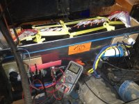
 o Verify ModB voltage through fuse - 94.6v
o Lift module and fuse assembly into case, towards drivers side
o Slide ModB(-) Balance harness through teflon tube and upper pass-through
o Bolt ModC(+) cable to upper fuse (threaded copper) with 
     - 2x zinc 3/8"-16 x 1.5" flange bolts, nylock zinc
     - Lube with Big Moose's anti-corrosion gel
o  Install upper thru-bolt#6, head towards front (must go on after ModB(-) cable)
     - hot dip galvnzd,grade8, 3/8"-16 x 8",(2) 2"flange washer,nut,nylock
     - Capture teflon tube that protects lower fuse-28s cable.  
     - Capture long side of shorter ModB retention strap 
o install upper fuse cap (won't fit on after 28s is in place)
o Press Mod B against bolts #4 and #6
o Slide rear ModB retention strap under cable, wrap around  3 lifting  straps
o Slide front ModB retention strap past fuse, wrap around 3 lifting strap
o  Install ModB Retention Bolt A (rear)
     - hot dip galvnzd,grade8, 3/8"-16 x 10"
     - 3" section of 3/8" ID Fuel Line, rubber over steel mesh=damping/insulation
     !! had to lever against side wall to get into place.
o Install upper thru-bolt#5, head towards front
   - hot dip galvnzd,grade8, 3/8"-16 x 8",(2) 2"flange washer,nut,nylock
   - Capture teflon tube that protects ModC(-) Upper to ModB(+) cable
   - Capture hasp side of ModB retention strap - check orientation
   !! Tight fit - I had to file front hole wider
o Install lower thru-bolt#3 over center plate, head towards front
     !! Need (2) flange washers
   - hot dip galvnzd,grade8, 3/8"-16 x 8",(2) 2"flange washer,nut,nylock
   - Capture hasp side of ModB retention strap - check orientation!
   !!  Tight fit - I had to file front hole wider 
o Install ModB Retention Bolt B (front)
     - hot dip galvnzd,grade8, 3/8"-16 x 10"
     - 3" section of 3/8" ID Fuel Line, rubber over steel mesh=damping/insulation
     !! had to lever against side wall to get into place.
o Install ModC balance pass-through and tighten both caps securely
o Insert ModC Balance harness through teflon tube and lower pass-thru
o Slide ModB(+) Balance harness through teflon tube and lower pass-through
o bolt fuse on ModC(+) terminal (all grade 8 hardware)
  3/8"-16/1.50"  bolt
  Thick/wide washer
  Thick/wide washer
   Nut
   Nylock nut (not grade 8)
   Locktite blue 
o  heat shrink ModC(+) fuse bolts and loose heat shrink other end
o bolt fuse on ModA(-) terminal
o heat shrink ModA(-) fuse bolts
o Bolt ModB(+) cable from ModC(-) Upper, using = WARNING
     !! Cable path Interferes with side bolts, back out partially
     - 2x M6x12mm, lock washer, one wide washer and one small washer 
     - Lube with Big Moose's anti-corrosion gel
     ===> THIS WILL COMPLETE THE CIRCUIT TO EXTERNAL TERMINALS
o tighten front retention strap, covers both ModB terminals
o reinstall drivers upper case bolt
o install crutch tip and acorn nut over driver's upper case bolt
o drive wedges between frame and box at both lower case bolts 
o Plastic between ModB and box front to reduce vibrations?
o Torque down all through-case bolts
o Terminate 28s balance harness and balance to verify connection
 
Happy Holidays, all!

We got let out of work early today, freeing up time for me to sort out a Christmas Eve post. :D Weekend before last I got hung up on the flywheel and CV joints, and the cleaning I did wasn't really postworthy. Last weekend however, I got the driveshafts off and removed the transmission. These are two more firsts for me, I am lucky that old VWs are so easy to work on, stuff just bolts together. Anyhow, I'm tipping a mug o' holiday brew to y'all, :D and on to my usual excessive load of pictures:
.

file.php

I cleaned the grime from the inside of the adaptor plate as best I could. Note the "hub" part of the adaptor kit, mounted to the motor shaft. It has (5) holes for the bolts that hold the flywheel.
.
.
01_IMG_1325.JPG

02IMG_1553.JPG

View attachment 22

04_IMG_1320.JPG

10 IMG_1448.JPG

11IMG_1309.JPG

12IMG_1545.JPG

15IMG_1449.JPG

16IMG_1455.JPG

17IMG_1459.JPG

18IMG_1458.JPG

19IMG_1456.JPG

20IMG_1119.JPG

25IMG_1127.JPG

file.php

Looking down at the front of the tranny from above and behind. You can see the bell-shape of the front mount underneath, in the center/left of the picture, but it is layered with grime. Note the three fins that support the "hockey stick" of the gear selector, this whole area is COVERED in grime, that will be cleaned off presently.

The leak is clearly from the nosecone at the top of the join with the transaxle body, and I haven't seen any cracks. I've read about (3) things that can cause this - Loose bolts, bad gasket, scarred mating surfaces.

Since the motor mounts were trashed and not actually connnected, the motor/tranny were simply bouncing around between the extremes of their constraints, and under hard accelleration the nose would lift so the shock load would be absorbed by the bolts at the top, where the leak is. I am going to try tightening these bolts and hope that fixes it.

As much as I'd like to take off the nosecone, replace the gasket and machine the mating surfaces, I've been struggling to keep a focus on the mission, which is to build an electric car, not to restore a Dune Buggy. I have a fantasy of tearing it down after I have the EV bits working, getting everything refurbished and repainted, but If I try to do both at the same time it will take much longer.

After all, I may find out this tranny is not up to the torque loads from an electric motor, and I'll have to replace it with one built for a heavier duty cycle.

.
.
View attachment 10

View attachment 9

29IMG_1479.JPG

31IMG_1530.JPG

32IMG_1538.JPG

33IMG_1540.JPG

40 IMG_1543.JPG

View attachment 3

42IMG_1476.JPG

file.php


So here they are, the tranny, motor, and driveshafts, ready to install in a clean rear end. This is the second time I have said this, but I think I am finished tearing things apart, it is much more rewarding to put things together!
.
.
Please ignore these duplicate pictures:
 

Attachments

  • 00_IMG_1324.JPG
    00_IMG_1324.JPG
    117.2 KB · Views: 4,731
  • 45 IMG_1548.JPG
    45 IMG_1548.JPG
    113.3 KB · Views: 4,731
A few videos:


[youtube]-mxq3WnfH04[/youtube]
Here I lifted and shook the tranny by hand, to show how the mounts were separated and completely ineffective.


[youtube]DdYza_Ilsmo[/youtube]
Which explains why this engine, which started easily and ran smooth as a top, bounced around like this old video above.

-JD
 
Do these VW transmissions not use any locating dowels? I've never seen one of these before, but have seen gearboxes from cars with them.

Just thought I'd ask since it'd be a shame to find out later that there were supposed to be some and you've got a vibration problem.
 
This is so amazing!! Thanks for sharing your project and in such a detailed way. Unbelievable :D. Your bus conversion was also a great read.

I usually hang around on the eScooter/eSkate forums (pretending to be young still!) but having owned classic VWs for 20 years this has inspired me the most to learn more about the EV scene and possibilities.

Please keep up the great work - and Yes - there should be 4 locating dowels for that transmission. Some people would say they are not essential but I say don't mess with Mr Volkswagen :D .... Well unless you're doing something crazy like this!
 
Hi Punx0r! :cool:

I remember reading about dowels for the older gland-nut flywheel, but I have the 5=bolt. Those are the only ones I know of, but I'm learning this stuff as I go. :mrgreen:


Thanks Benj! :D I am concerned that this thread's detail might be too much for some, so I am glad that it suits you. I am trying to post things that I wanted to know when I was researching this project - weights, what stuff looks like, how it fits together, etc... Plus I am near retirement and my memory isn't what it used to be, so its helpful to document the choices I made and why. You sound like you know VW's - how clean do I need to get the mating surfaces for the nosecone gasket below? I scraped the old gasket off with boxcutter, it is pretty smooth but there is sort of a black varnish on it, dont know if it has to be polished mirror-smooth.


Fingers, I agree - maybe I should mount a wheel to the tailshaft. :lol:

Anyhow, here is the latest installment to this series, titled "Remember when you had free time?"

00 IMG_1900.JPG

View attachment 10

View attachment 9

03 IMG_1939.JPG

04 IMG_1940.JPG

06IMG_1914.JPG

07IMG_1918.JPG

08IMG_1968.JPG

09IMG_1969.JPG

10IMG_1919.JPG

11IMG_1925.JPG

12IMG_1929.JPG
 
I've gotten into the habbit of using a plastic kitchen pan scouring pad (with some solvent or WD40) for cleaning old gasket/sealant from aluminium mating surfaces. It can be a little slow, but will not damage anything, so is nice and safe (I use abrasive paper on steel parts).
 
because of nice people like you, I don't have to do a beautiful, expensive car conversion now. I can sit here and pretend I'm doing it because you are so detailed in your blogging! Looking great. I may request a test ride
 
Oatnet!

I really appreciate the effort that you have put forth. Great Pictures and Commentary!

Tommy L sends....
 
Back
Top