-
Howdy! we're looking for donations to finish custom knowledgebase software for this forum. Please see our Funding drive thread
You are using an out of date browser. It may not display this or other websites correctly.
You should upgrade or use an alternative browser.
You should upgrade or use an alternative browser.
1 Cell Inverter Project
- Thread starter hilllzofvalp
- Start date
hilllzofvalp
10 mW
- Joined
- Dec 25, 2010
- Messages
- 20
I'm not sure those are available in high volume, I rather use some dc dc chip and put it all on one pcb with the inverter.
I'm not sure going from 5 to 12V is worth that 30% reduction in on resistance. For the space of the extra components for 12V I might be able to afford to double my 20V direct fet bank and distribute the cooling surface area and get similar or lower on resistance total.. right?
What gate driver do I need to drive 6 of these 20V direct fets in parallel @mxlemming ? They are 158nC max, 108nC typical.
Nevermind, it looks like the direct fets might be discontinued. Now I'm interested in sTOLL 40V. 150nC, still same problem. How many can I paralell with which gate driver?
Last edited:
hilllzofvalp
10 mW
- Joined
- Dec 25, 2010
- Messages
- 20
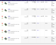
WHat about these babies?
I'm pretty sold on these. 33nC? wouldn't that allow me to run like 10 of these in parallel with standard drivers? Also logic level.
I'm pretty sold on these. 33nC? wouldn't that allow me to run like 10 of these in parallel with standard drivers? Also logic level.
Last edited:
JackFlorey
100 kW
Sure that's doable (it's what Polulu does) just more design work.I rather use some dc dc chip and put it all on one pcb with the inverter.
A 30% reduction in on resistance pays big dividends in efficiency, size and cost. And it's just not hard to boost to 12V.I'm not sure going from 5 to 12V is worth that 30% reduction in on resistance.
Then you need 2x the drive power, will generate more EMI (larger current loop, more AC power) and your layout gets more difficult.I might be able to afford to double my 20V direct fet bank
I used an earlier generation of those. They had two problems:WHat about these babies?
1) The forward voltage of their body diodes is much higher (on the order of 2-3 volts.) So reverse biasing them (to reduce shoot-through) will lead to very rapid heating. Which leads to the second problem:
2) Those packages have close to zero thermal mass. So if you do start heating them up they will melt, then vaporize, the solder holding them to the board, and pop themselves off. We had this happen several times.
They've gotten better, so if you are careful with shoot-through timing, use additional catch diodes and are careful about thermal design they can work.
hilllzofvalp
10 mW
- Joined
- Dec 25, 2010
- Messages
- 20
Can you show me how to maximize the amount of the GaN fets in parallel with the proper gate driver and catch diodes? Zero idea what I'm doing.
mxlemming
100 kW
- Joined
- Jul 17, 2020
- Messages
- 1,129
Look at my thread on MESC GaN and IMS boards. That shows a good way to lay the driver out. I was running 50A/FET with not much issue, but I had to click them to a lump of aluminum. More FETs really just means wire them all in parallel with a gate resistance per FET. You're so far away from parasitic turn on at 1s that I really doubt you need to take any precautions atall.Can you show me how to maximize the amount of the GaN fets in parallel with the proper gate driver and catch diodes? Zero idea what I'm doing.
I think for this though I'd definitely err on the side of large copper heavy FETs with a 12V gate. GaN is an extra hassle you just don't really need. Much more sensitive to exact gate voltage and the footprint is cursed.
hilllzofvalp
10 mW
- Joined
- Dec 25, 2010
- Messages
- 20
Will I still be able to run at 20kHz to make the motors nearly silent? Seems like onewheel only manages 18kHz. Still prettty high, but I wonder if they chose that because of switching losses
Why am I drawn to the GaN.. why do I want the GaN...
Why am I drawn to the GaN.. why do I want the GaN...
Last edited:
mxlemming
100 kW
- Joined
- Jul 17, 2020
- Messages
- 1,129
20kHz is really slow. I run 30+kHz on my bike (beware VESC would call that 60kHz!) you can easily run 20k with standard silicon. GaN is good for 100s of kHz.Will I still be able to run at 20kHz to make the motors nearly silent? Seems like onewheel only manages 18kHz. Still prettty high, but I wonder if they chose that because of switching losses
Why am I drawn to the GaN.. why do I want the GaN...
Similar threads
- Replies
- 5
- Views
- 2,050


