18650 battery Kit development and discussion[testing done]

DrInnovation said:
Nice design, just they type of thing I'd want for an 18650 build. Understand that you can only make so many design. Not sure if it will matter.. but those of use stuck back at 24v.. would be interested in something 8s.. But here is my business arugment -- the others all variations seem to aimed at the same pack voltage. 8S would be a size for another pack voltage which could give a broader market to help recover your design costs ;-D

Series configurations are easier. No cost involved in tooling. I might lok into it if all goes according to plan. Isnt 24V 6S?
 
agniusm said:
DrInnovation said:
Nice design, just they type of thing I'd want for an 18650 build. Understand that you can only make so many design. Not sure if it will matter.. but those of use stuck back at 24v.. would be interested in something 8s.. But here is my business arugment -- the others all variations seem to aimed at the same pack voltage. 8S would be a size for another pack voltage which could give a broader market to help recover your design costs ;-D

Series configurations are easier. No cost involved in tooling. I might lok into it if all goes according to plan. Isnt 24V 6S?

I guess if its 6s 7s or 8s depends on if you consider LiFePo4 or LiPo and if you use the nominal (3.2/3.7) or the high (3.6/4.2).
Since SLA's are generally above 24v I expected that 24v systems were good upto about 28 and probably safe to 29.

For LiFePo4
3.2*8 = 25.6 nominal 3.6*8 = 28.8 at max v
for LiPo
3.7*7s = 25.9v nominal 4.2*7 = 29.4 max v
LiPo 4.2*6=25.2 so closer to 24 at max but down to 22v at nominal value.


Though more about your design.. couldn't one just leave some of the series slots empty so a box that that is 10s just has two empty rows becomes (mayeb with a wire/bar continuing circuit) to be used as 8S (or three rows for 7s). Maybe that is what you meant above about no costs in tooling. For that matter parallel slots could also be left empty.. am I missing something?
 
I am not past thinking what every one will do. It is getting designed for given configurations. One could chainsaw a tv to make it smaller and I dont care :)
What I care about is to make it proper quality battery kit without spaghetti, duck tape and blobs of solder.

I am working parallel on arduino test system. It will have temp sensor, presure sensor and accelerometer and during the test it will record all data to sd which I will then make into diagrams for us to decide how it did.
 
Bit by bit getting my testing rig made. The software is ready, still need to wait for some sensors.
20141015_154839.jpg

This is the pressure sensor i will use to see how polyurethane performs over time:
20141015_151117.jpg

I have also purchased nut rivet tool to make almost flush covers which came today, and the quality is good, 44USD:
20141015_140425.jpg

Here is some 4mm stainless on 2mm aluminium plate:
20141015_140438.jpg

Here is a test on 10mm planned thickness material:
20141015_140412.jpg

20141015_140416.jpg

Spade%2520connector%2520addon.png
 
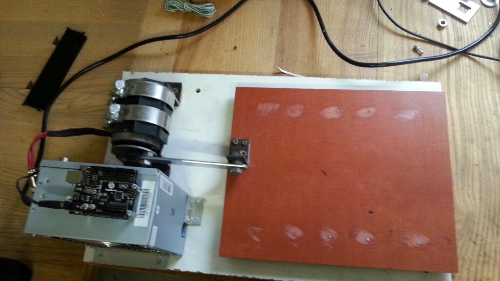
It's great to see someone doing some vibration testing on a homebuilt machine :)

I don't know much about the subject, but having use a shaker table I can offer the following.

One revolution of the motor will be one cycle. I appreciate this will actually be accelerate-decelerate-accelerate-decelerate, but that's the convention - one cycle is where you end at the position you started.

Vibration levels are expressed as displacement, velocity or acceleration, either as RMS, peak or peak-to-peak. RMS seems fairly common (giving the "power" of the vibration).

The motion of your machine should be sinusoidal and you can calculate the vibration level based on the frequency (3000rpm/60) and displacement (stroke length).

Permissible levels for rotating machinery (excluding internal combustion engines) are generally less than 10mm/sec (peak). Our machine runs at a little under 50mm/sec.

It would be interesting to get a rough idea of the vibration (perhaps just the frequency) found in a non-suspension bicycle ridden on a typical road and use this to set your shaker table. I don't know if it's possible to use the accelerometer in a smartphone to do this.

I would run the test for much longer than 8 hours unless it's much more severe than the vibration found in end-use (hence the usefulness of having a rough idea how your shaker table compares to real life). Think that 1000 miles ridden at 20mph is 5000 hours.
 
Good stuff.
I could fit my arduino setup on the battery and take it for a ride off-road. I can set data collection intervals of up to 10ms to get logged to Arduino and 3 axis forces are recorded. (To save data efficiently it is recorded RAW so i need to get them converted in Excel or something and them make charts)
As for testing period, 8 hours will be plenty, i am not testing this for a lifetime of the kit but rather if electrical parameters change in such conditions, and 8 hours of such vibrations will be tens of times of magnitude of real world it is my guess and besides i am a small operator with no sidekick with funding :)
 
\/ampa said:
agniusm said:
It would be hard to achieve. Existing holders are designed with the gap. I dont see why you would want it dense as it is good to have a gap for cooling reasons.
If the air can move on top and bottom where the spot-welding is. Than it is for the new high power 18650 cells no problem to stay cool.
So i would also consider it useful to have only a 1mm spacing and cells shifted for maximum dense.
Its always better to overbuild a battery to higher Wh than the actual need. For longer cycle life.

Hi battery forum! I am new to ev making. Im planning to make a 8ah pack of li-ion 18650 or maybe a smaller cell for a skateboard. I was hoping i could solder them all together and also solder balancing leads and then glue the battery pack to a hole cut in the board. I read the batteries expand and contract- would it be too much to sink them and the wires fully in epoxy? I imagine so but how about even partially? seems a simple way to secure them as well as my esc and receiver. Or maybe a mix of something with epoxy would be better? Would the vibrations be too much for the esc and receiver?

When charging with just the balance leads would that take much more time? Id like to keep this simple.
 
Bare copper as a bus bar is probably not a good idea, unless you can somehow guarantee no air comes between the copper and the cell. Copper oxidizes in the presence of air and forms copper oxide, a non conductive layer. For pretty much every connector ever, copper is coated in gold or tin to avoid corrosion.

If you use dielectric grease, how can you be sure it won't shift/move away from the contact area? Or what about the grease moving between the cell and the copper, because of long term vibration, forming an insulator.

Copper_wire_comparison.JPG
 
Not sure how I missed this thread until now , but glad to see it now.

My 20ah cell's have been decent for me , but just to bulky. I am pretty close to buying a 18650 battery and having the vendor do the welds
until I came across this thread. My requirements are minimal. Less then 100V so 18-22S. Prefer 20ah+ and needs to fit into my phasor frame.

Technically i can use my lipo until summer so if what your working on here can meet my requirements put me down for one.

I have seen first hand the quality of your work.
 
dnmun said:
Allex said:
I have my cells orginized like that , 20s14p and I am drawing 130-150Amps from them(peak).
The pack is no more than 45C at most so I never felt the need of cooling.
Hi-drain LG HE2 cells
So with your current design would give me less Whrs and probably put more stress on the cells because I have to use less "p" which gives me more heat and less life cycles.

you already gave up a lot of life cycles by soldering such huge wires to the cans. there is absolutely no reason to use such a huge conductor to tie the cans in parallel but it appears that everyone who decides they can build a battery does it.

your battery delivers the current in series through the pack so the parallel connection does not carry any current.

all the heat that went into the cans when you soldered it has shortened the cycle life already.

H
How big must the conductor be? I haven't figured what cells I want to use but with something as small as 30volts and 5ah with 18650...
So the connections in series carry no current? So those going to the esc, in parallel, need to be thicker and the others, in series,..how big a conductor do you need if it carries no current?
 
Nelson37 said:
IMO a component, solderless kit to produce a modular e-bike battery using these cells would be a very marketable item.
The same was told about my fused 18650 kit. After one year of development, when I already had something to sell - all interest was gone. And I kept my promise to keep same price as from day one of development.
So now I encourage you all to be very cautious before investing your time and money.
 
agniusm said:
While waiting on parts build my shaker machine to test battery kit in vibration enviroment. I dont know how to put it right but if motors rpm is 3000, than the vibration is 100Hz is my thinking. What would be best frequency to test out if batteries performance does not change? Time pf the test and frequency of the vibrations?
[youtube]5XuCIShD30E[/youtube]

I have a shaker test of my own that I plan to use once I build packs. My electric lawnmower!
I'll build a 3p10s pack and let-r-rip for a bunch of cycles. It's perfect because the battery will be powering it's own shaker tester, and it provides a good drain so the cells will heat up. :-D
 
agniusm said:
None at the moment. Not much interest was expressed so I am working on it when I can.


This place is moody. I think there is a lot of interest. This is what one bike builder supposedly patented. It would go over great. Being able to. Repair a pack or simply rebuild with soldering or welding or stating from scratch every time would be amazing. I know a half dozen users off the top of my head that would jump in. It's hard for the non tevhnical to stay excited but damn dude, I am. I need a way to keep packs sustainable. Repairable by me. We often find deals in batteries but building is a pain in the you know. Getting the bits together to do a decent job is a long and costly project. Then you get the experts who have the critical reviews but no time to create a diagram, or picture, or detail to learn from. I get dnmun'so point but if there's no pattern and we have limited experience, it's just as tiring hearing the criticism as reading the threads about half assed builds. Grrrrrrrr. I'm trying. The is exactly what I need. There's another fellow on YouTube who recently poked in here who made a compression pack by dimpling copper sheets and having plastic guides or spacer racks cnc'd out of plastic. But non of which is accessible. He get all sorts of hits and interest. I'm rambling now but I think you'd generate a ton of interest.

What do you need to get excited again? I need to figure out a scheme for 24v and 36v. Us old farts don't need 48, 72 and bigger super packs. We just want a reliable method of building packs without solder and welders.

Rock on! Please!!! Sorry about the crazy iPad typing...
 
agniusm,

I think there is a lot of interest- I for one am looking forward to what you end up producing and would likely be interested in buying at least one or two.

A couple of key points in reply to circuit, and this is not meant to take away from your product, as I think you made a quality design for a certain scenario. However I don't think you got a lot of interested due to your design requiring a spot welder and as a result was not repairable in the way that this is intended to be. Once someone has a spot welder, nickle strips and 18650 holders are easily obtained otherwise, so you restricted your market to a very small pool of candidates.

A "tool-less" 18650 kit that allowed a user to pop in 18650 cells, monitor those cells and easily disassemble for individual cell replacement is the holy grail and I personally think will sell like hotcakes. Ultimately I think this is fairly price sensitive as well, under $100 for a kit IMHO is the sweet spot. Ideally perhaps multiple versions, starting significantly less with just the core parts as mentioned by Nelson37. I personally would be interested in the core components, but I know others that would love the whole enchilada kit and can just buy and toss in cells of their choosing.
 
Under 100USD, i doubt that's possible. I'd need to sell hundreds. Sure injection molding would reduce the cost and all but think the cost of dies. As i said, working on it as i can, hobby style as i don't see it making something viable for me to be worth my time. There are tons of ppl who could jump on this. Snath gave pretty detailed idea for someone to jump in.
 
I would be really cool if someone did an open plan that one could take to the local cmc shop and have fabricated. Maybe that's unrealistic. I'd pay for a 10s, 6p-7p box. Maybe that's still unrealistic? Even the wimpy box that came with the bicycle would be an improvement. Maybe a well designed that could leave empty cell slots for a number of configs. I'm working with the 18650 spacers and they suck. Reselling the NOS cells with a thicker skin makes them really tight.

Here's a difficult design, for me... but I like the idea...
https://www.youtube.com/watch?v=kBMnHYaymHU
 

Attachments

  • Screen Shot 2015-02-12 at 2.38.21 PM.png
    Screen Shot 2015-02-12 at 2.38.21 PM.png
    115.3 KB · Views: 3,154
  • Screen Shot 2015-02-12 at 2.38.00 PM.png
    Screen Shot 2015-02-12 at 2.38.00 PM.png
    117.7 KB · Views: 3,154
  • Screen Shot 2015-02-12 at 2.40.37 PM.png
    Screen Shot 2015-02-12 at 2.40.37 PM.png
    123.8 KB · Views: 3,154
You can build like that in your garage for yourself but selling this?! It has to be more professional. DIY folks are scarce on cash and this is the main problem. Sure, if i would be able to get in OEM with large quantities it would make sense to work hard on the project and consumer price would be acceptable, but there is always a risk and at the moment it does not calculate for me to throw money at something that might be just another "money in a bin" situation. Well see.
I am just amazed, how there is none such kit available on the market, surely Chinese are scanning these forums as well:)
 
Yeah, those solutions are clearly visible on their pack with wires disconnecting. Would you mind sharing Chinese solder less, spot weld less solution they have? I am constantly scanning Chinese market and have not discovered such thing as of yet
 
Just give me some time to track down the link.

EDIT: Ok, here it is. Wireless design :) But if I see it well, they still have to weld the positive side of cells which are on topmost position.

http://akbattery.en.alibaba.com/productgrouplist-220504360/48V_Series.html

http://akbattery.en.alibaba.com/product/1526882743-220504360/48V_40Ah_High_quality_Lithium_Motorcycle_Battery_Very_safe.html

http://akbattery.en.alibaba.com/product/1468356473-220504360/48V_40Ah_E_scooter_E_motorcycle_Special_vehicle_Rechargeable_Battery_Pack_Lithium_Ion_Battery_Pack.html
 
Back
Top