8.4v NiMh Li-ion Replacement Help (Newbie)

Bad_rabbits

1 µW
Joined
Nov 20, 2019
Messages
3
Hello all,

Firstly, thankyou for taking the time to read this. I hope you won't be offended by me posting here - there may well be other forums more suitable, however this has been the only forum I have been frequenting over the last year, I've grown greatly interested in the subject of homebuilt battery packs. I'm not an E-biker (yet) - my primary interest is has been in building large capacity powertool battery packs. Projects completed so far - zero.

I'm not completely ignorant when it comes to DC electricity, and thanks to this forum, have learnt a moderate amount about Li-ion batteries and pack building.

I have an old Thermal imaging camera that I am trying to make good. Essentially it needs a power source... and since my last accident, a new display - though this was always a planned upgrade.
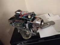
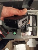
IMG_20191121_021529.jpg

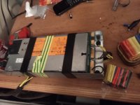
The unit was originally powered by an 8.4v NiMH battery pack - the same variety as used in some Icom 2 way radios.

I understand that the NiMH pack provides a very linear source of power, and although replacement packs that took 10 x AA Batteries are also available (5S2P... Is my nomenclature correct?) - they are advised against due to the sensitive nature of the electronics.

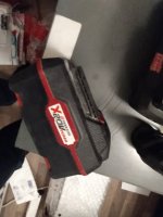
To cut a long story short, I was planning to rebuild the enclosure for this camera, utilising a "Parkside" brand 18v nominal power tool battery as a power source. Not the ideal type of Lithium battery, In know (high discharge, relatively low capacity), but I have plenty knocking around. I also have a 3D printed adapter allowing me to mount it on the underside of the unit - and it just looks like it was meant to be there.

When bench testing I used a cheap 5a rated DC-DC adjustable Buck converter, model XL1405 to provide 8.4v from the Parkside battery. Something went horribly wrong.

I know that the camera doesn't pull anything like 5a, even on startup, so I can't imagine what the issue is. I tried a second XL1405 (Always buy cheap chinese stuff several at a time) and had the same issue. Everything checked out on the multimeter, but the camera didn't like it one bit. Distinct toasty smell.

Since then the CRT monitor/viewfinder has packed in.

Thankfully there is a BNC outlet included in the wiring, which I had always intended to use to rig up a higher resolution monitor - this particular 2nd Gen TIC is quite capable and the inbuilt CRT screen doesn't do it justice.

I have tried the XL1405 unit with a variety of power supplies and always get the same results. 12v SLA, 12VDC PSU...

I am able to run the camera for short periods using 12VDC. Since the accident in fact, a 9V power source doesn't seem to cut ther mustard. I'm slightly concerned about the long term damage that may have been caused here.

I feel like I must have made some rookie error, does anybody have any suggestions? Any thoughts whatsoever would be greatly appreciated.

View attachment 5
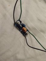
IMG_20191121_021807.jpg
View attachment 3
IMG_20191121_021723.jpg
IMG_20191121_021702.jpg
IMG_20191121_021556.jpg
 
Please excuse the formatting errors, and the double post - I'm quite anxious not to edit my original post as when I tried that last time, all of my attachments disappeared.

I did do some reading, of course it is preferential to have the images uploaded directly to the ES server rather than to link to an outside source. I will ensure that any further posts are better formatted however, apologies.

** UPDATE**

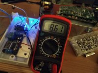
While trying to organise the chaos that is my humble abode I came across an old project, with a slightly less powerful but also supposedly 'tried and tested' DC-DC voltage buck module (LM2596). The previous module is an XL4015 (previously miss-spelled, apologies).

Anyway, I thought why not rig it up for 10 seconds and see if it doesn't cause the same problem. Voila!

It's rated for 3A. Let's assume 2A - which I know from experience is enough to run this camera. Excellent.

IMG_20191121_060635.jpg

Does anybody have any idea what may have been responsible for the problems with the XL4015 modules? (Shoddy manufacture aside?).

Anyway, best wishes. If anybody is interested I'll keep you updated as I go.
 
Bad_rabbits said:
I understand that the NiMH pack provides a very linear source of power, and although replacement packs that took 10 x AA Batteries are also available (5S2P... Is my nomenclature correct?) - they are advised against due to the sensitive nature of the electronics.
If the AA pack was only 5s, then that would only be 7.5v max when new, and dropping as they drain, so I don't see why it would be advised against vs an 8.4v original pack (presumably 7s), which would be as high as 9.8v during the peak charging voltage for NiMH, assuming they used the common self-balancing mechanism of charging the NiMH till the excess charge was dissipated as heat. And the original pack would probably run down to as low as 7v before running out of useful power, so the AA pack would still be within that range, if it's 5s.

Unless the camera's design causes it to be damaged or operate incorrectly when voltage is too low, without some automatic shutoff system, there's no reason it should have a problem. And if it did have this design flaw, it would *still* have a problem with the NiMH pack when discharged down very low. :?


When bench testing I used a cheap 5a rated DC-DC adjustable Buck converter, model XL1405 to provide 8.4v from the Parkside battery. Something went horribly wrong.
EDIT: I missed the pics of the XL1405 board module, somehow, when reading your first post, so ignore the bits about you building the circuit...but the rest still applies--wrong design, bad parts, etc., could all still cause AC components in the output that ccould cause problems with a pure-DC device not built to tolerate that.

What circuit did you build around the XL1405 chip to operate it? If it's not built right (wrong or no inductor, etc), it's possible that switching noise could be high enough voltage spikes to damage stuff down the line, if there's not enough filter capacitance inside the camera to damp that.

Also keep in mind that as you go up in voltage for the chips' output, you should derate the current output appropriately. It should still supply more than 4A at 8.4v, but probably not 5A (probably not your issue, but it depends on the circuit design you used around the chip).


I have tried the XL1405 unit with a variety of power supplies and always get the same results. 12v SLA, 12VDC PSU...
What exactly is the circuit outputting? Is it purely 8.4v DC, no ripple or AC component? A battery powered device may be very intolerant of anything other than flat DC, because it's design doesn't require it to filter anything--the battery doesn't have any ripple. ;)


I am able to run the camera for short periods using 12VDC. Since the accident in fact, a 9V power source doesn't seem to cut ther mustard. I'm slightly concerned about the long term damage that may have been caused here.
That probably means that the internal PSU of the camera is damaged or destroyed; it probably had a simple boost converter for at least some voltages, running off the battery pack's voltage, and now it's switching pass transistor (probably thru an inductor) is shorted, so it's passing power directly thru (or else the camera wouldn't work at all, probably).

Anytime you use higher voltage than a device was designed to use, even by a tiny bit, you risk destroying it, if the parts and/or design they used were not rated above what the original supply could output. :( Many devices are rated to handle at least short overages on the supply, but some are not, especially battery powered units (because they dont' expect anything higher than battery voltage could possibly ever reach the innards). Some of them can't even tolerate batteries being inserted backwards even momentarily (even though that's a very common thing for people to do with replaceable cylindrical types, and instantly fry critical parts from the reverse voltage. :/


Unless you already have schematics for it, you'd probably have to trace out and draw up the circuitry for the input sections of the camera's power supply, to see what it *should* work like, and hten measure stuff out to see if it still does work that way, or if it's behaving differently than that design would dictate. That would tell you if the PSU in it is damaged, and might help you repair it if there's no components damaged so extensively that you can't tell what they are anymore.
 
Looks like you replied while I was typing my post above (takes me quite a while, sometimes :oops:)

Bad_rabbits said:
While trying to organise the chaos that is my humble abode I came across an old project, with a slightly less powerful but also supposedly 'tried and tested' DC-DC voltage buck module (LM2596). The previous module is an XL4015 (previously miss-spelled, apologies).

Anyway, I thought why not rig it up for 10 seconds and see if it doesn't cause the same problem. Voila!

It's rated for 3A. Let's assume 2A - which I know from experience is enough to run this camera. Excellent.
Do these statements mean that the camera works correctly using the LM2596 board pictured, while it still does not using the other module?

If so, then assuming the output voltage is correct for the other chip's circuit, while under load, I'd suspect a problem with ripple or outright AC on the output. You'd have to test for that to know for sure.

If the viewfinder/screen still doesn't work, then it probably means there's still damage to whatever internal voltage converters the camera has that part runs from, but could simply be damage to the screen electronics themselves.
 
amberwolf said:
Looks like you replied while I was typing my post above (takes me quite a while, sometimes :oops:)

Nothing wrong with that, you did after all provide a highly concise response to my various dimwitted remarks. Thankyou kindly!

And Yes... 5S AA... Really not sure how that slipped past me. I'll have to look into this... Let me also try and dig out the source that had me so convinced about the Metal Halide packs... perhaps it was something unique to the pack itself.

amberwolf said:
If the viewfinder/screen still doesn't work, then it probably means there's still damage to whatever internal voltage converters the camera has that part runs from, but could simply be damage to the screen electronics themselves.

That probably means that the internal PSU of the camera is damaged or destroyed; it probably had a simple boost converter for at least some voltages, running off the battery pack's voltage, and now it's switching pass transistor (probably thru an inductor) is shorted, so it's passing power directly thru (or else the camera wouldn't work at all, probably).

Yes. I'm quite gutted I must admit. Not good news now I've had the chance to do a bit more basic diagnosis...

It seems the CRT monitor (module) not functioning is symptomatic of a wider failure. These machines were built using a mish mash of components... So a voltage spike (or short), or non linear current has taken out just enough of the components to make it, perhaps scrap.

For example, there is a spinning rotor between the Germanium lens and the image sensor - this is something to do with the refresh rate... I'm quite ignorant as to the precise process. The motor that spins the rotor is rated for 12v... and is working. On the other hand, the rear of the image sensor unit has a small fan and heatsink - this is also integral to the working of the sensor. When I rigged it up to an external monitor I quickly noticed cold objects were not being detected - this led me to the fan, which I rigged to an 18650 (unsure of the required voltage but as near as damnit to 3.5v seemed a safe bet). Surely enough the sensor started picking up colder objects.

Anyway, there are a number of components not getting the juice they require. I think you're quite right;

amberwolf said:
Anytime you use higher voltage than a device was designed to use, even by a tiny bit, you risk destroying it, if the parts and/or design they used were not rated above what the original supply could output. :( Many devices are rated to handle at least short overages on the supply, but some are not, especially battery powered units (because they dont' expect anything higher than battery voltage could possibly ever reach the innards). Some of them can't even tolerate batteries being inserted backwards even momentarily (even though that's a very common thing for people to do with replaceable cylindrical types, and instantly fry critical parts from the reverse voltage. :/

Unless you already have schematics for it, you'd probably have to trace out and draw up the circuitry for the input sections of the camera's power supply, to see what it *should* work like, and hten measure stuff out to see if it still does work that way, or if it's behaving differently than that design would dictate. That would tell you if the PSU in it is damaged, and might help you repair it if there's no components damaged so extensively that you can't tell what they are anymore.

He he... Schematics. My understanding is that there are hardly any two of these units built quite alike.

My plan of attack, when I have the time, is to separate the 4 primary boards and do a bit of detective work in the following order;

1) Familiarise myself with SMT fuses - then see if I can find any. I know they exist.
2) Try to evaluate what the occasional transformer on the 3 logic boards are supposed to be doing, vs what they are doing.
3) Finally look at the PSU PCB. I've heard of people scrapping 2 of the 3 logic boards and the PSU PCB with cameras that are all but the same and ending up with a working unit 1/4 the size... I have a hunch that the problem is after the PSU... Also with my lack of knowledge I think it will be easier to work from the front end backwards - A coil of wire on a board full of IC's and SMT components just seems like a good place to start eliminating.

The original unit DC-DC voltage regulator is supposed to be acceptable. Shoddy manufacturing perhaps?

Thankyou again for replying. I do sincerely appreciate it.

These cameras fluctuate so much in price / availability and they have a bit of a following. If I can't resurrect it, I'll certainly learn a bit in the process.

Thanks again, you're a superstar.
 
Back
Top