www.recumbents.com
10 kW
http://www.recumbents.com/wisil/e-bent/sensors
I had been using this Astroflight 3210 RC motor with an RC controller (ESC). RC controllers do not use sensors, because RC motors are designed to always run at high RPMs. E-bike motors on the other hand run at low RPMs when starting. It always annoying me that the motor would cough and hiccup until I got up to about 10 MPH (at which point it would of course launch my bike like a rocket).
Ian (burtie) has been making sensor conversion kits for sensorless RC motors. Sensors tell the controller when to send a pulse of power to a particular phase of the motor, which makes the motors run much better at low RPM, and can make them run more efficiently at high RPM.
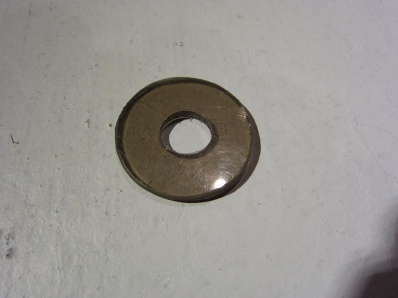
Bertie's kit comes with a circuit board, a washer, a sheet of paper with the black/white patterns on them, and a piece of balsa wood.
The idea is to space the washer out about 5mm from the rotor on the axle. Instructions said to use the balsa and silcone, but I decided to make a washer out of Lexan (polycarbonate) for a spacer, and use JB Weld to glue it all together.
The Astro motor has an aluminum spacer between the rotor and the bearing. The washer and Lexan spacer sit on this 1/2" OD spacer.
Because the washer has a bit of slop on the aluminum spacer, I used a punch to make a series of dents close to the ID of the washer, which closed the gap.
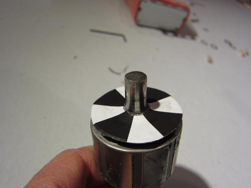
Here's the spacer and washer glued to the rotor. I roughed up all surfaces with fine sandpaper before glueing.
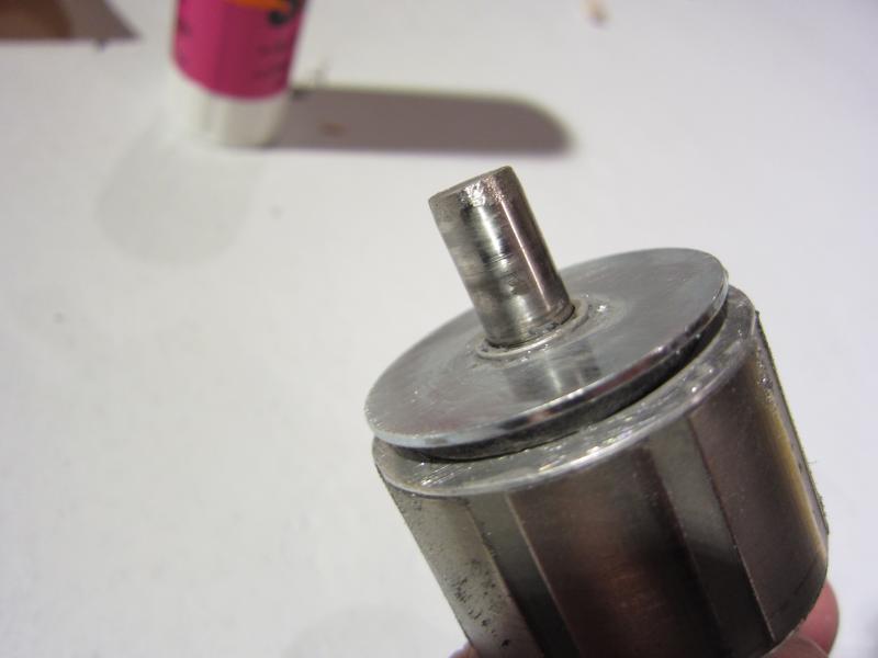
I cut out and glued the sensor pattern to the washer.
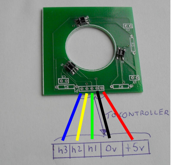
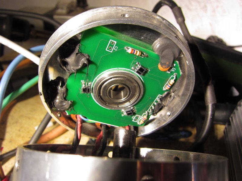
Added the wires to the sensor board and mounted the circuit board to the inside of the motor cover. Right now it is just a friction fit.
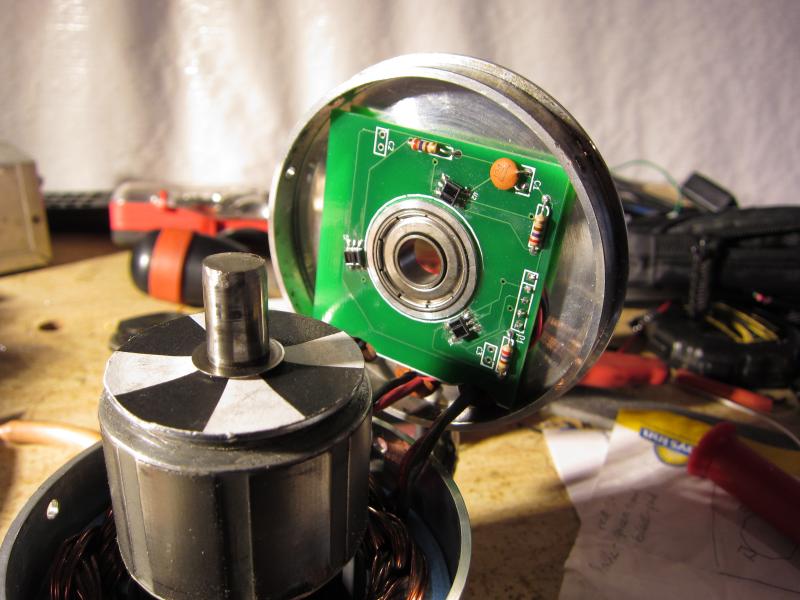
Adjusted the circuit board until there was about 2mm between the sensors and the pattern.
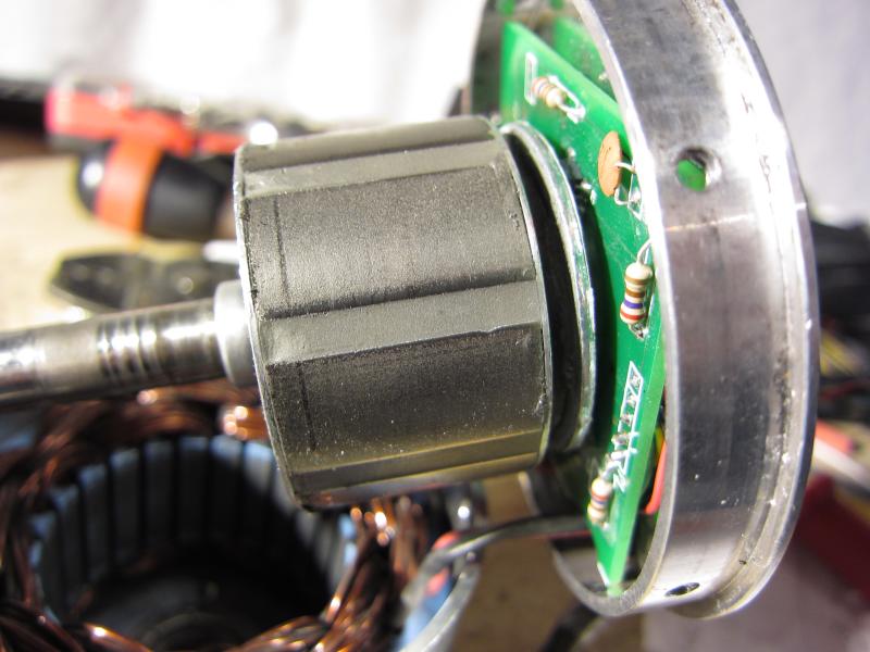
Sealed up the motor temporarily as the circuit board will probably need to be twisted a couple degrees to adjust the sensor timing.
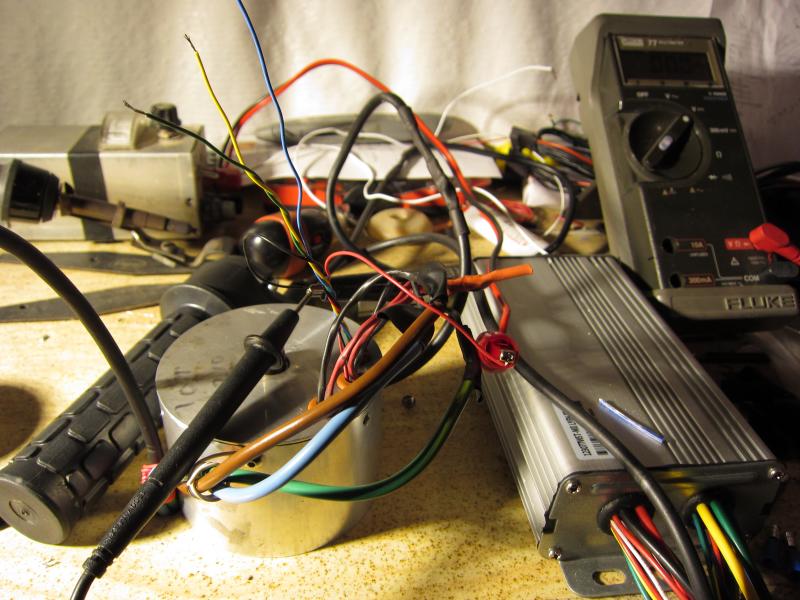
Used a 5V power supply connected to the 5V and Gnd wire of the sensor board to ensure that the sensors switch between about (about) 0V and 5V. It works!
-Warren.
I had been using this Astroflight 3210 RC motor with an RC controller (ESC). RC controllers do not use sensors, because RC motors are designed to always run at high RPMs. E-bike motors on the other hand run at low RPMs when starting. It always annoying me that the motor would cough and hiccup until I got up to about 10 MPH (at which point it would of course launch my bike like a rocket).
Ian (burtie) has been making sensor conversion kits for sensorless RC motors. Sensors tell the controller when to send a pulse of power to a particular phase of the motor, which makes the motors run much better at low RPM, and can make them run more efficiently at high RPM.
Bertie's kit comes with a circuit board, a washer, a sheet of paper with the black/white patterns on them, and a piece of balsa wood.
The idea is to space the washer out about 5mm from the rotor on the axle. Instructions said to use the balsa and silcone, but I decided to make a washer out of Lexan (polycarbonate) for a spacer, and use JB Weld to glue it all together.
The Astro motor has an aluminum spacer between the rotor and the bearing. The washer and Lexan spacer sit on this 1/2" OD spacer.
Because the washer has a bit of slop on the aluminum spacer, I used a punch to make a series of dents close to the ID of the washer, which closed the gap.
Here's the spacer and washer glued to the rotor. I roughed up all surfaces with fine sandpaper before glueing.
I cut out and glued the sensor pattern to the washer.
Added the wires to the sensor board and mounted the circuit board to the inside of the motor cover. Right now it is just a friction fit.
Adjusted the circuit board until there was about 2mm between the sensors and the pattern.
Sealed up the motor temporarily as the circuit board will probably need to be twisted a couple degrees to adjust the sensor timing.
Used a 5V power supply connected to the 5V and Gnd wire of the sensor board to ensure that the sensors switch between about (about) 0V and 5V. It works!
-Warren.