Adding sensors to a Astro 3210 motor

liveforphysics said:
johnrobholmes said:
The EV logic amp limiter would not solve the half throttle heating issue, it may make it worse by causing more partial throttle use.
Bingo.
I keep bouncing against that "fet-wall" don't I. :p :lol:

Ok, here's another idea... why not just use a smaller gauge wire to the motor from the ESC to prevent it from sucking enough amps to burn-up the ESC?

Is this possible? :twisted:


:idea:
 
deVries said:
liveforphysics said:
johnrobholmes said:
The EV logic amp limiter would not solve the half throttle heating issue, it may make it worse by causing more partial throttle use.
Bingo.
I keep bouncing against that "fet-wall" don't I. :p :lol:

Ok, here's another idea... why not just use a smaller gauge wire to the motor from the ESC to prevent it from sucking enough amps to burn-up the ESC?

Is this possible? :twisted:


:idea:

Any amount of power it reduces reaching the ESC will be directly released as heat in the wires. You could of course make an elaborate high resistance high wire cooling suface area system to ensure high voltage drop in power transmission, but this just results in wasted battery energy of course.
 
gwhy! said:
AussieJester said:
I'm with Matt after the initial sync the throttle control is smooth as my trikes. I just give it a lil more at the start and the sync aint even an issue, i have no probs riding through my local car park and shopping center (they allow me to do this one of the perks hehehe) with stabilizers down doing less than walking pace. Only problem i see is the volt limitation...oh and the fact they blow up haha...

KiM


Horses for courses :D Im assuming this is on the flat'ish, but how much more have you got to give it to pull away on a 15% grade hill :?: would it be possible/controllable :?: this is where the sensorless controllers fall down they need to be consistent and the rider should not have to worry about how much do I need to give it to stop the rc esc from popping.

LoL i have nothing but hills here GWhy I never worry about popping it i feed in the throttle fast but steady, my mate did however manage to pop the "something" when he returned the Turnigy Meter was way lower peak amps than i have gotten it too HOWEVER it is still not verified that the ESC is fried, the throttle interface is blown soon as i get the EVlogix throttlizer ill be trying the HV110 to verify. The throttle interface had one blown cap and a trace vaporised :lol: When i replaced this and repaired the trace though there was a short in it so haven't been able to test the esc. I'll get video when i am up and running again doing slow walking pac figuyre eights in a car park shall i? increasing and decreasing speed slowly and quickly? Can even do it on a hill if you wish? Has no probs powering off a hill from a standstill at all GWhy do it pretty much every ride i go on :)

KiM
 
AussieJester said:
gwhy! said:
AussieJester said:
I'm with Matt after the initial sync the throttle control is smooth as my trikes. I just give it a lil more at the start and the sync aint even an issue, i have no probs riding through my local car park and shopping center (they allow me to do this one of the perks hehehe) with stabilizers down doing less than walking pace. Only problem i see is the volt limitation...oh and the fact they blow up haha...

KiM


Horses for courses :D Im assuming this is on the flat'ish, but how much more have you got to give it to pull away on a 15% grade hill :?: would it be possible/controllable :?: this is where the sensorless controllers fall down they need to be consistent and the rider should not have to worry about how much do I need to give it to stop the rc esc from popping.

LoL i have nothing but hills here GWhy I never worry about popping it i feed in the throttle fast but steady, my mate did however manage to pop the "something" when he returned the Turnigy Meter was way lower peak amps than i have gotten it too HOWEVER it is still not verified that the ESC is fried, the throttle interface is blown soon as i get the EVlogix throttlizer ill be trying the HV110 to verify. The throttle interface had one blown cap and a trace vaporised :lol: When i replaced this and repaired the trace though there was a short in it so haven't been able to test the esc. I'll get video when i am up and running again doing slow walking pac figuyre eights in a car park shall i? increasing and decreasing speed slowly and quickly? Can even do it on a hill if you wish? Has no probs powering off a hill from a standstill at all GWhy do it pretty much every ride i go on :)

KiM
:mrgreen:
Hi KIM,
I didnt know that you were having problems with your throttle interface. So something has blown then :?
Once rolling I have no doubts that the controller will be fine'ish, its that very initial static load that could be the killer and the more static load i.e hills the more it is likely to pop. Come on just face it sensorless is just second rate for bikes that need to start from a dead stop, Get your halls and sensored controller sorted, It takes all the guess work out of "WHEN is my rc esc going to blowup" :wink:
 
gwhy! said:
Get your halls and sensored controller sorted, It takes all the guess work out of "WHEN is my rc esc going to blowup" :wink:

As you know i tried that didn't work i shall be looking into it again dont fear, i want the bike working so i can use it though not sitting there while i try and get it working, i cant afford to have both, sensorless just works mate, the infineon didn't. Not about to waste another few hundred on something i don't know if i can get working, where as couple hundred gets me another sensorless setup that i know i can plug straight in and ride within minutes. Get me a bolt on sensor setup with a working controller etc etc and ioll use it till then i'll be more than happy MORE than happy using the sensorless i see absolutely no advantage of the Infineon for my riding, technical riding like you do i can see the advantage. If i had a HV160 from the start i think i would still be riding fact the HV110 is a lil under powered for my application but was all that was avaialle at the time.

KiM

p.s to add to the that, i can't even get the Infineon software loaded on my PC to alter the controller settings!!! once more GWhy...the Castle Creations plug and play.
 
Hi,
swbluto said:
Hey, I climb 400 foot hills with 1.5 kW of power AND at 20% throttle and my ESC hasn't blown yet and it's been running for about 1.5 years now. Of course, I also added some cooling to the ESC. The ESC really needs extra cooling to survive. What happens is that if it overheats, and then one fet pushes just enough current to self-destruct and it's all over. If you prevent it from over-heating, that doesn't happen.
Would you please explain how you added cooling to the ESC?
 
MitchJi said:
Hi,
swbluto said:
Hey, I climb 400 foot hills with 1.5 kW of power AND at 20% throttle and my ESC hasn't blown yet and it's been running for about 1.5 years now. Of course, I also added some cooling to the ESC. The ESC really needs extra cooling to survive. What happens is that if it overheats, and then one fet pushes just enough current to self-destruct and it's all over. If you prevent it from over-heating, that doesn't happen.
Would you please explain how you added cooling to the ESC?

Sure, see http://endless-sphere.com/forums/viewtopic.php?f=35&t=7638&start=45#p136805 .

It's much better when you actively cool the CPU heatsink - the ESC has NEVER got above 120 degrees fahrenheit (Although the mosfets themselves may have reached somewhere in the high 100's like 180, but that's no biggie for mosfets.). To actively power the heatsink, a simple DC to DC converter is all that's needed. Mine only requires 100 mA to power.

To demonstrate moreso the point of cooling, the castle website states their ESCs are rated for 5 mph of air cooling. If they're in still air, the current rating declines significantly (By something like 60% of their original rating - I'd have to check to get exact numbers). So, A heatsink REALLY helps out with this because it decreases the thermal resistance and increases the heat capacity. A powered heatsink helps out even much much more. It's like exposing the ESC to a 60 mph air flow.
 
Hi,

recumpence said:
That must be a matter of personal preference because I have never, EVER had anything but buttery smooth low RPM operation from my RC ESCs. That being said, they blow easily at low RPM. So, in that regard, low RPM sucks. ;)

Matt

GGoodrum said:
With low throttle demands, it stutters a lot, from a stop. If I just crank on the throttle from a stop, it stutters and then blows up. This happened twice, and that's when I stopped using this setup.

deVries said:
Could one or both of you explain what each of you are doing differently to get opposite results??? :?

Thats the question I wanted answered when I started this thread:
http://endless-sphere.com/forums/viewtopic.php?f=28&t=18792#p273943

Mitch said:
D's Kona requires excellent low speed performance and I haven't heard him complain. OTOH Ypedal (whose bike should have more reduction) isn't happy with his Castle.
I think I finally figured it out (I'll post this on the other thread so hopefully further discussion won't drag Burties thread any further OT).

Matt uses high kv motors with 3 stage reductions (probably at least 30:1 total?). Gary is using the lowest kv and the least reduction (about 9:1) he can to make a single stage reduction possible. And Ypedal's build doesn't have sufficient reduction.
 
I am working on a mountainbike setup and i am looking for a sensored motor and controller (middle drive) Sensored is important as described before when starting uphill with heavy drivers. What controllers would fit best a sensored 3210 or 3220 Astroflight?
 
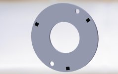
I drew up a little pcb shape (no traces yet) that will fit in the 3230 beast that Matt has made. 20mm ID, 44mm OD with the sensors place on a 42mm OD circle. Once I get some hall sensors I will do a bit of testing to see where neutral timing is.


Any suggestions on a quick place to start for the positioning? Mine is a 6 wire, it looks like people are placing the sensors where each phase pair is pulling off the stator.


Looks like time for me to get my rotary table set up. Having a little arc on the backplate would make it super easy to adjust timing from the outside.
 

Attachments

  • 3230 beast sensor pcb.jpg
    3230 beast sensor pcb.jpg
    26.5 KB · Views: 601
Actually, John, the 6 mount holes for the rear motor plate could be milled do the rear plate can be rotated with the PCB rigid mounted to the inside. That would make timing a piece of cake.

Matt
 
Yeah, that would be a pretty slick option for production. Milling slots where the smaller mount holes are would be easier and faster for me, and allow for a larger range of adjustment just in case I am totally off on my first guesses of where neutral is. If I can't get my rotary set up satisfactory I may have you make another back plate for me.
 
This new 3230 variant still has the same diameter rotor, right? If so, this should work for all 32-series, correct?

As Luke has pointed out previously, if you want to do D-Y switching, there needs to be two sets of hall sensors, offset 15 degrees from each other.

-- Gary
 
Hi,

Matt said:
Actually, John, the 6 mount holes for the rear motor plate could be milled so the rear plate can be rotated with the PCB rigid mounted to the inside. That would make timing a piece of cake.

GGoodrum said:
This new 3230 variant still has the same diameter rotor, right? If so, this should work for all 32-series, correct?

johnrobholmes said:
The bearing pocket is different than the standard astro, but the pcb could likely be made to work for both.
But once the design is nailed down using the 3230's wouldn't it be pretty easy for Matt to mill plates for all the 32-series?
 
GGoodrum said:
This new 3230 variant still has the same diameter rotor, right? If so, this should work for all 32-series, correct?

As Luke has pointed out previously, if you want to do D-Y switching, there needs to be two sets of hall sensors, offset 15 degrees from each other.

-- Gary

It's 30 electrical degrees between delta and wye.


Also, as far as getting something 'perfect' or whatever, neutral timing would roughly be the best you can get. However, neutral timing is a far cry from ideal for our situations. The guys running lower motor RPMs will want the sensors with less advance, the high RPMs guys looking for maximum power will want lots more timing advance, and the super watt-miser guys may want to even retard below neutral timing to simulate a lower KV motor.

It's really a pretty dynamic thing. That's why it's critical we get a magic box that can take a neutral sensor timing position, and electronicly shift the timing as best suits the riding situation.
 
Within a year we may even have controllers that will switch over to sensorless automatically. At least I hope so. Sensors are good for startup, and that is really about it.
 
johnrobholmes said:
Within a year we may even have controllers that will switch over to sensorless automatically. At least I hope so. Sensors are good for startup, and that is really about it.

That's fairly easy to do right now with a Xiechang type controller. Keywin sells a little board to make these controllers work as sensorless ones; essentially just a set of comparators that do a zero-crossing detection on each of the phase wires. They simply hook up to the Hall wires on the controller, and there's no good reason why you couldn't just fit a three pole changeover switch to switch from sensored to sensorless mode as you wished. If you wanted to get fancy, then you could add a bit of simple switching logic to make the changeover automatic at any preset rpm.

Jeremy
 
I had no luck with kewin's sensorless boards getting the motor to behave with any load on it at low RPMs.
 
liveforphysics said:
I had no luck with kewin's sensorless boards getting the motor to behave with any load on it at low RPMs.

No, I know they are problematic down at low rpm and start-up, but the idea would be to run in fixed timing sensored mode up to a reasonable rpm, to give good start up and low speed torque, then switch to sensorless mode for medium to high speed running. The Halls will give the solid position feedback needed for start up at low speeds, and by switching to sensorless you get the ability to do timing adjustment on the fly, just by varying the threshold at which the zero crossing detectors operate. This is similar to the way that pre-digital electronic ignition systems managed to get advance; they used a sinusoidal sensor and varied the threshold on a comparator with rpm.

Jeremy
 
The sensorless 18fet I got from Lyen starts smoother than my sensored controllers over 90% of the time. On the rough starts it must be just the wrong magnet/stator position. The smoothness may be due to the high pole count, 48 magnets/51 stator slots.

I had them rig it for both sensored or sensorless operation, but on sensorless it wouldn't run right above 500rpms. Current went up, power dropped, and the motor didn't sound right. Plugging the halls in didn't make any difference at all, so I don't think the either/or implementation worked correctly.
 
I finally got a motor here and running! Woo Hoo!

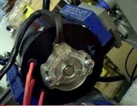
It's been a week long process since I got the motor but it purrs now! I had to build a hall sensor module and liked the idea of keeping it out of the heat and flux of the motor. The sensor holder bolts to the end cap and the magnet trigger ring bolts to the end of the shaft. The only mods necessary to the motor are a 4mm drilled and tapped hole in the end of the shaft, and two 4mm tapped holes in the end cap. I also spent two days trying to get my computer to reprogram the infineon with no luck and finally tried it on an XP computer and it worked on the first try.
I hooked everything up, totally guessed on wiring and sensor position and it spun right up, right direction and everything! I noodled with the timing to get the no load current as low as possible and to get it running smoother but that was it.

Here's a video:
http://www.youtube.com/watch?v=atY2JbXDik0

The no load current is still too high so I'm going to have to sort that one out. It's as low as I can get it by adjusting the sensors. I'm also not certain that my CA is properly calibrated. I put in 3.8mOhm for the shunt value but still seeing a -1A reading with no throttle. I have to sort that out, then set up the dummy load and start playing with the timing tool. I'm so psyched!

Specs:
12 Fet Infineon
Astro 3220 4 turn
custom hall sensor module
turnigy lipo
large screen CA
thumb throttle

Volts= 45.8
RPM range = 205 - 7930
No load full rpm amps= 9.0


It's on now!
:twisted:
 
Hey Mdd,

This looks really neat. I love the way you have made that hall sensor unit and screwed the rotor into the end of the motor shaft.

MddsAstro.jpg

How did you construct the magnet ring?

And the neat plastic case around the whole assembly?

Much respect 8)
 
Back
Top