bobmutch
100 W
Is my position in 1. right or wrong?
Can I have some feed back 2. please?
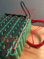
1.Here is an example that looks good but in reality B- wire is only connected to the 2nd last cell (see pic below; pic from https://www.myah.com/blogs/diy-energy/18650-battery-safety-guide ).
I see people doing this all the time. The current sees the wire that is soldered from the 2nd cell to the 7th cell as a parallel busbar, and the connection of the B- wire is only connected to the 2nd last cell.
View attachment 1
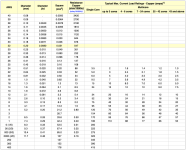
2. Here I would suggest 9 PVC-insulated multi-core (7-24 core) 14 gauge wire (good for 70A) and they can be soldered to the nickel strip before it is laid. These 9 wires should be the same length, twisted together, and soldered to a connector.
If that seems like an over kill then use 4 PVC-insulated multi-core (7-24 core) 12 gauge wires and attach them equally spaced to the 9 cells. This would be good for 60A. (See pic below; pic from https://www.engineeringtoolbox.com/wire-gauges-d_419.html


