Bestechpower BMS

Yes, I use a balancing charger.

I only have the monitors on while I'm actually riding. When I've done riding, I fold the bike and put it in the car, and I *have* to disconnect the batteries to do that, the bike is much heavier if they're attached.

I have a 40 amp fuse which I'm hoping would blow in the case of a short circuit. It's a standard car-type fuse, so I'm pretty confident it will work.
 
dnmun said:
the D167 charges through the P- connection. it does not have a separate charging mosfet.

I received the D167 BMS and i dont understand how the BMS will cut the voltage when the LVC kicks in. Battery + and charger + are plugged in the same port. Battery - and charger - in the other.
 
virtuhal said:
dnmun said:
the D167 charges through the P- connection. it does not have a separate charging mosfet.

I received the D167 BMS and i dont understand how the BMS will cut the voltage when the LVC kicks in. Battery + and charger + are plugged in the same port. Battery - and charger - in the other.
no. battery is connected directly. there is only GROUND divided. there are 3 connections: Battery -, Charger -, and Controller -. no positive.
 
izeman said:
no. battery is connected directly. there is only GROUND divided. there are 3 connections: Battery -, Charger -, and Controller -. no positive.

the diagram at the data sheet shows only two connections. There are some remarks:
¨Charge, Discharge at same Port
P+ = B+ / Charge + / Discharge +
P- = Charge - / Discharge -¨

There are no ¨P+ or P-¨written on the board.
 
izeman said:
ok. please post a picture. i only own those d131 types. so those may be different. sorry.
Agniusm posted some pictures at:
http://endless-sphere.com/forums/viewtopic.php?f=14&t=50207#p754944
 
the BMS is a fuse in the negative lead of the battery. it has nothing to do with the positive end of the battery.

if you are not familiar with how a BMS works or how it should be wired up you should stop and take time to learn.

henry will have sent you a data sheet with the BMS.
 
dnmun said:
the BMS is a fuse in the negative lead of the battery. it has nothing to do with the positive end of the battery.

if you are not familiar with how a BMS works or how it should be wired up you should stop and take time to learn.

henry will have sent you a data sheet with the BMS.

I have a Signalabs working for three years. The wiring is different from this unit.

You said this BMS acts like a fuse. So B- comes from battery negative. The other connection goes to charger/controller negative. Right?
 
yes these are not like the signalab BMS at all. everything is different.

yes, you connect the charger and the controler negatives in those two holes on the outside edge and the negative terminal of the battery goes to the B- spot.
 
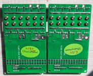
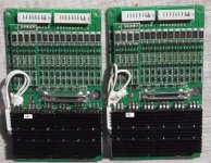
I try to figure out the difference between the 20s HCX-D167 boards with 4.28V cutoff (the left one) and 4.20V (the right one). 4.28V seems too much for me..maybe I can use them in a Pack with LG cells rated for 4.3V :?
 

Attachments

  • 4.20V vs 4.28V back.jpg
    4.20V vs 4.28V back.jpg
    511.2 KB · Views: 2,270

Attachments

  • 4.20V vs 4.28V.jpg
    4.20V vs 4.28V.jpg
    485.8 KB · Views: 2,267
htx, that helps me more. the 682 measures 6,8kOhm (68*10^2), the 685 measures 6,0MOhm. The difference is a factor of 1000. strange

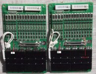
another one: on the 4.20V board there is something missing: a cap and a 308 resistor
 

Attachments

  • 4.20V vs 4.28V.jpg
    4.20V vs 4.28V.jpg
    486.9 KB · Views: 2,270
i think you have them backwards in the description. i am not sure why you ordered two different balancing voltages and why you would wanna have a balancing voltage of 4.28V which is really high.

on my D126 the balancing shunt transistor comparator/gate driver is labeled GCLC for 4.20V

on my D167 it is GCLD for 4.20V

for the lifepo4 with the 3.60V balancing voltage it is R2RB

so i would recommend you use the one that has the GCLK on it for the 4.20V balancing voltage.

i would not recommend you use the other one that is set to 4.28V balancing voltage. but you may wanna test it but in that case you will have to raise the charging voltage to 20x4.28=85.6V instead of 84V.

that source gate resistor is labeled 685 on mine which is normal for a source gate resistor, you should measure yours with the voltmeter. i doubt if it is 682.

i also do not have the resistor and capacitor on the other end. the adjacent resistor on mine which is connected in parallel reads 202.

my HVC/LVC comparator/gate driver chip is labeled G3MD and that is for LVC=2.80V and HVC=4.28V and this what i recommend people use for lipo.

your HVC/LVC comparators are labeled G3MJ and G3FJ? what does the data sheet he sent you say for their HVC and LVC voltages.
 
They just send me wrong boards the first time so i got replacements. Now i got these laying around, but i paid €12 each for customs :(
The salesman from Bestech told me that there are only 2 different versions. 4.20V and 4.28V. I told him that i want 4.20V, that's all. After I received the 4.28V boards and told them they were wrong he sent me these which took some time :roll:

Thanks for clearing things up. I thought they use the same opamps with different resistors on each version. Didn't know that they use different comparators. Any idea how i can find a datasheet about these?

As said, i measured the gate? resistor 6.8kOhm (labeled 682) and 6.0 MOhm (labeled 685)

HVC=4.28V and this what i recommend people use for lipo.
I ordered 4.20V since 4.28V is too much for Lipo IMO.

i would not recommend you use the other one that is set to 4.28V balancing voltage
what is balancing voltage? i see it on the specs but dont understand what this may be. Just ordered 4.20V.

And I still think that I could use these wrong boards with cells rated for 4.3V max like the LGs. Any (safety-) reason i shouldn't?
 
the balancing voltage is the voltage where the comparator turns on the shunt transistor and diverts current around the cell.

the HVC is the setpoint where the charging mosfet is turned off to prevent overcharging.

you should use the 4.20V for the balancing voltage and use the 4.28V for the HVC since it is required to have the LVC be set to 2.80V.
 
if you do not charge to full voltage, such as if you charge to 4.15V initially, then it is not gonna be able to balance the cells in capacity so then if you later charge them to less than full voltage, such as 4.15V/cell then the cells will not be balanced in capacity after that.

lipo is good about staying balanced once you initially balance them. so if you wanna balance the pack initially and then reset the charger voltage to a lower voltage so they do not charge to too high a voltage for you then they will remain fairly well balanced for a long time and if you monitor the voltages of the cells on a regular basis then you will see when the resting voltage after charging starts to drift, then you can charge them up to full voltage and balance again, then reduce the charging voltage again after that. you should be able to go for a long time in between the balancing charges.

the reason i recommend the 2.8V for the LVC is because it helps protect from over discharge by accident which i consider the biggest risk. using the 4.28V for the HVC is not an issue since it is rare for a cell to climb to that level when charging a balanced pack to the normal final voltage. there is no risk if one of the cells climbs to 4.28V.
 
ah thanks. now i now why i always sticked to the OZ890 :p still a lot to learn here. I soldered extra balancing plug to my board that i will need now from time to time. I thought the BMS will do that for me, just like the oz890 did. Maybe I should dig it out for that purpose and use two of them to balance my 20s pack.
 
if you have the D167 which is set to 4.20v for balancing then you can use it to balance the pack initially, as i said, then reduce the charging voltage if you do not wanna charge the cells to 4.15V after that so then your charger voltage would be 83V instead of 84V when you wanna balance.

since it has only 100 ohm balancing shunt resistors it will take a long time to balance so you could monitor it while balancing and then use a big power resistor on the highest cells to get the pack to balance faster.

then you would be able to bulk charge under the BMS so it would be protected from overcharge and from over discharge. you would have short circuit protection of the output then too.
 
that is not worth a lot. I dont want to open my charger to change the charger voltage. It does output 83.8V max. I dont have a balance charger that can do 20s anyway. I only can use simple RC balancers, seems like my only option.
 
crossbreak said:
that is not worth a lot. I dont want to open my charger to change the charger voltage. It does output 83.8V max. I dont have a balance charger that can do 20s anyway. I only can use simple RC balancers, seems like my only option.
call me tomorrow and we can discuss that on the phone if you wish
 
Back
Top