bluetooth BMS?

ElectricGod said:
I'm working on upgrading an 18 fet motor controller ATM for MORE POWER!!! Based on what I know from doing the same thing to a 12 fet, I should see something like 6.5 - 7kw. :)
i have a 12FET doing 4kW w/o getting warm, so asking 7kW from a 18FET is surely doable.
 
izeman said:
ElectricGod said:
I'm working on upgrading an 18 fet motor controller ATM for MORE POWER!!! Based on what I know from doing the same thing to a 12 fet, I should see something like 6.5 - 7kw. :)
i have a 12FET doing 4kW w/o getting warm, so asking 7kW from a 18FET is surely doable.

All my 12 fets are doing 4kw continuous from the battery and they "warm up to ambient" and that's about it. My expectation is the 18 fet will add another 2kw at least. How far have you pushed your 12 fet controller? I run at 170 phase amps and 60 battery amps with no issues. I did try running at 190 phase amps, but the motor was already delivering max torque so I turned down phase amps to 170. I can probably go lower with no torque loss. Still, the controller never got warmer than ambient. This is on AOT290's. My next controller upgrade will run AOT2500's since it will need to run at 32S/131 volts. I will be building 2 18 fet controllers with them and 2 18 fet controllers with CSD19536KCS 100 volt mosfets. Only the best mosfets please!

I've ordered 2 more of the 16-20S smart BMS to upgrade with IRF4110's and larger shunts...2 watt shunt this time so current reading is correct.
 
can't remember as it was some time ago, but i guess i should have been around 200A phase.
btw: my 6 FET lebowski controller runs 150A phase w/o breaking a sweat. and this is just because the current sensors are 150A types. so this is the limit. the FETs are IRFB4468 (2mOhm), so not the small to220 case.
 
I got 2 of this other style smart BMS in 32S, 300 amp version. I have had no time to power them up yet, just take one apart and take pictures and look up a few parts. It's essentially the big brother to the 24S LCD smart BMS that was posted here earlier. The below picture is the 24S version powered up. I have one of those too. The 32S version looks effectively the same...just a little larger. I have 8 LIPO packs that will be put together into a 32S pack for testing the BMS. I won't be able to deliver 300 amps to the BMS...more like 100 amps max, but I can at least bench test.

BMS%20LCD%20screens%201.jpg


The balance board is decently made with dual CPU's on it. One is an atmel 328 and the other is a smaller 8 bit atmel cpu. The board has a dedicated DC-DC converter and opto isolators protect the LCD, balance board and mosfet boards from each other. Cell balancing typically is done with chemistry specific IC's. These BMS use a different method. They are highly flexible and can balance any battery chemistry. As a result typical LION IC's would NOT work here. They chose to use 74HC595 latches instead. They remember their last state and essentially turn on and off the mosfets that do the balancing. All BMS do this in some fashion. Cell monitoring happens in the CPU, not in the chemistry specific IC's. The atmel 328 tells which latch to turn on or off for balancing. This allows the BMS to balance at 1 volt or 4.5 volts per cell or whatever is meaningful to you and has been set in the software. This design completely eliminates the need for a LIFE or LION or LTO or SLA or whatever. There is no need for a chemistry specific BMS, just set it to the parameters of your cell chemistry and you are done.

32S%20smart%20BMS%20-%20balance%20board%20-%20top.jpg

32S%20smart%20BMS%20-%20balance%20board%20-%20bottom.jpg


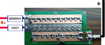
There's no access to the P- connection. Same for the 24S version. I'll have to get longer screws so that I can add copper on top of the mosfet tabs to add P-. Grrr! All you get at those solder tabs is B- and C-...what a waste. If you don't mod the BMS, you have to charge and discharge via C-...I'll pass! The copper reinforcing is done well, solders to each mosfet and over laps the wire bond pads.

32S%20smart%20BMS%20-%20mosfet%20board%20-%20top%20side.jpg

32S%20smart%20BMS%20-%20mosfet%20board%20-%20copper%20busses.jpg

32S%20smart%20BMS%20-%20mosfet%20board%20-%20shunts.jpg


This is truly confounding! This is a 32S BMS. That means it realistically needs to handle upwards of 140 volts depending on cell chemistry. So why does it have 100 volt mosfets (HY45N10's) on the C- side? Why no access to P- where it has 150 volt IRF4115's? There is no part of 100 volt mosfets that are OK in a 32S BMS designed for 140 volt continuous operation. I can't imagine what the manufacturer was thinking!

32S%20smart%20BMS%20-%20mosfet%20board%20closeup%20HY45N10%20mosfets.jpg
 
izeman said:
can't remember as it was some time ago, but i guess i should have been around 200A phase.
btw: my 6 FET lebowski controller runs 150A phase w/o breaking a sweat. and this is just because the current sensors are 150A types. so this is the limit. the FETs are IRFB4468 (2mOhm), so not the small to220 case.

I have boards and MCU's to make a couple of Lebowski's, just not had time and parts to do any building yet. It sounds like you did exactly what I had in mind. I wanted to use TO-247's and unless I found something to trump the venerable 4468 was going that route too in 12 fets. I am looking for a stupid amount of wattage for a future bike build that will run on a 50kw motor wound for 9 phases. The Lebowskis are part of that. I have purchased an Alien Power 12090 with damaged windings that I will rewind with 14 awg and 9 phases and then ran from 3 controllers. It should be an interesting project to develop. The 12090 is the test bed for the real 50kw motor. I have things to learn and try.
 
ElectricGod said:
There's no access to the P- connection. Same for the 24S version. I'll have to get longer screws so that I can add copper on top of the mosfet tabs to add P-. Grrr! All you get at those solder tabs is B- and C-...what a waste. If you don't mod the BMS, you have to charge and discharge via C-...I'll pass! The copper reinforcing is done well, solders to each mosfet and over laps the wire bond pads.

I have the 24S version that I am almost ready to install... but after reading your post, I am considering adding P- first. Before I do, I would like to ask two fairly novice questions:

1) What is the benefit of separating P- from C-?
2) Is the modification simply a case of soldering a copper wire to the trace connecting the HY045N10 screw tabs (I am guessing this is the FET's drain since I have not had much luck finding the HY045N10 datasheet yet), reinforcing the trace with a copper strip, and linking this directly to the load's negative - as shown in the image below?

BMS_P-.jpg
 
cglass said:
ElectricGod said:
There's no access to the P- connection. Same for the 24S version. I'll have to get longer screws so that I can add copper on top of the mosfet tabs to add P-. Grrr! All you get at those solder tabs is B- and C-...what a waste. If you don't mod the BMS, you have to charge and discharge via C-...I'll pass! The copper reinforcing is done well, solders to each mosfet and over laps the wire bond pads.

I have the 24S version that I am almost ready to install... but after reading your post, I am considering adding P- first. Before I do, I would like to ask two fairly novice questions:

1) What is the benefit of separating P- from C-?
2) Is the modification simply a case of soldering a copper wire to the trace connecting the HY045N10 screw tabs (I am guessing this is the FET's drain since I have not had much luck finding the HY045N10 datasheet yet), reinforcing the trace with a copper strip, and linking this directly to the loads negative - as shown in the image below?

BMS_P-.jpg

Which is better? More resistance or less resistance? OK...not enough information, becasue both are correct in the right circumstance. In an EV, you want the maximum amount of voltage and current possible exiting the battery pack and making it to the motor and NOT getting lost/wasted in other places. This comprises a significant efficiency improvement or loss and can almost always be detected as heat. Heat is caused by the process of restricting current flow and therefore reduced electricity available to make you go.

a. The motor isn't a perfect conductor and has internal losses...heat is the result. You want to use a motor that is efficient so it wastes as little electricity as possible as heat.
b. The wires to and from the motor or controller, battery, BMS and elsewhere are not perfect conductors. Some electrical loss as heat happens in them. You want to use large wires that have very low resistance since they will lose some amount of electrical power as heat but less than other options.
c. The motor controller has mosfets. They may have higher or lower internal resistances. More resistance is always going to create more heat than less resistance in the mosfets. Mosfets always have some amount of resistance and it can't be helped. Use mosfets that have a very low Rds such as the AOT290 or CSD19536KCS and others so that you minimize heat losses due to mosfet resistances.
d. If you have interconnects between things, use connectors that are very low loss such as 5.5mm bullets.

Geez, that took forever to get around to answering your questions.

1. So then P- vs C-. In any BMS, you have 2 sets of mosfets. One set controls charging and the other discharging. You want mosfets in a BMS so that in the event of an over load or pack depletion event the BMS can protect your valuable batteries. However, there's no need for putting multiple sets of mosfets in series as this does not create extra safety, just extra losses. C- (charging) mosfets pass current through the P- (discharge) mosfets to get to the battery. No one cares about a little loss when plugged into the wall outlet, just when riding on batteries. Imagine if you are running your EV from C- and therefore through the 2 banks of mosfets. In series that's 2 sets of resistances that are generating heat. Now if you eliminated the C- mosfets, now your heat and electrical losses have also dropped in half. So then powering your EV from P- is more efficient than is powering it from C-. You can run your EV from C-, but it's less efficient.

Really BAD, crappy, awful mosfets would have an internal resistance of .1 ohm. Pathetic mosfets (HY3410) have an internal resistance of .04 ohms. Decent ones have an internal resistance of .004 ohms and really good ones like the CSD19536KCS have a resistance of .0025 ohms. Less resistance in the mosfets means less loss as heat. This is very much a game of less is more and waaaay less is waaay more. Regardless of whatever mosfets are in your BMS, the fewer of them in series creating resistance to current flow and heat losses the better!

2. Yes...you need copper (IMHO) under all those nuts on the same side as the other copper busses. Put the copper under every single one of those nuts that holds down a mosfet. Over lap it onto the P- solder pad. Solder it down to the P- tab. I wouldn't worry about soldering the copper down elsewhere. You have a zillion screws holding it firmly in place. It would be a good idea however to tin the entire copper strip so that it can't oxidize and then conduct less. Yes your picture is exactly how I would connect power to the EV.

I want to say one last thing...
You CAN use the BMS without the added copper. However resistance is losses and copper is a great conductor with minimal losses. The bare traces on the board can handle a considerable amount of current, but IMHO, they are not really adequate. If they were, why did the manufacturer beef up the other power traces? I think you see my point.

I'm a stickler for losses I can prevent...such as missing copper, crappy mosfets, under sized wires, cheap solder, low grade connectors, cheap bearings, low pressure tires, lossy chain drives, dragging brakes and so on. I don't even use a transmission or derailleurs becasue they add losses. It's my opinion that an EV should be all about the fun factor, efficiency and no pollution and making that happen for as long as possible. Losses as a general statement are BAD.
 
I may have asked you this before.
For those of us using only c. Can I connect my load to the shunt?
Looking at pictures it is the connection below p.
First thought was to jumper disch Mosfets, but then I remembered that bms checks for shorted Mosfets and opens the other set for protection.

I don't trust the bms to not get me stranded, but would like the ammeter to work on discharge.
 
ElectricGod said:
I got 2 of this other style smart BMS in 32S, 300 amp version. I have had no time to power them up yet, just take one apart and take pictures and look up a few parts. It's essentially the big brother to the 24S LCD smart BMS that was posted here earlier. The below picture is the 24S version powered up. I have one of those too. The 32S version looks effectively the same...just a little larger. I have 8 LIPO packs that will be put together into a 32S pack for testing the BMS. I won't be able to deliver 300 amps to the BMS...more like 100 amps max, but I can at least bench test.
i have this one as well and this is why i asked for what a good replacement would be for the mosfets.
 
today i did some more oberservations:

my battery is connected to B- and P-. C- is not used at all. all shunts are connected to B-, so this is how current is measured.

.) the PC/mobile app shows the charging FETs as always engaged. even though this is NOT true. there is no closed circuit between the C- drain/source, and the gate shows 0V as well.

.) when you connect a charger to the P- then the BMS's B- FET's are turned on, no matter if the K1 switch is engaged or not. this is GOOD, as it lets you charge the battery with the BMS power turned off. as soon as you disconnect the charger the B- FETs go down (open circuit) again.

.) if you close the K1 switch ALL FETs are powered (close circuit). so both C- and B- are closed circuit to B-. that doesn't make sense at all.

.) balancing is another strange thing: there are two options: "balance enabled" and "charge balance". both can be checked. but only one of them can be active. if you select "charge balance" then it start balancing once it reaches the set voltage for balancing DURING the charge process. it stops balancing immediately once you disconnect the charger - even if "balance enabled" is checked.
"balance enabled" though ONLY works it "charge balanced" is unchecked. it will balance as long as the voltage of any cell is higher than the balance voltage entered.

.) balancing NEVER happens on more than HALF the cells. only even or uneven cell numbers are balanced at the same time. this HALFS the give balance current, or DOUBLES the theoretical balance time, however you will see it.

none of these things are show stoppers, but maybe important to know.
 
ElectricGod said:
I haven't looked at all, but can you find the actual BT module used on these BMS? We want the specs and pin out for it. There's likely to be an enable pin and a sleep pin on the module. Power is likely to stay on all the time and the enable and sleep wires put it in low power mode.
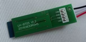
can't say anything about the BT module itself, and the part number may be on the down side, covered by the green board.
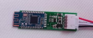
the whole board is named LH-BT05 V1.2 and it looks like a HM-10C to me according to this page: http://www.martyncurrey.com/bluetooth-modules/

regarding my high power drain i never thought of disconnecting the BT module at all from the BMS to see if it is the culprit. once my balancing is done i will disconnect it and test the drainage again.

here are two pics:


IMG_20180228_172446.jpg


IMG_20180228_172456.jpg
 
and here are some measurement with and without the BT module.

.) in standby (or not connected to any mobile phone and blue LED off) the BT module consumes 100uA or 0.1mA @11V. so that's more or less notthing ;)
.) when connected to a phone it uses 9mA @11V. still very little and nothing to be concerned about. so around 100mW.

then i measured current of the BMS with and without BT module connected, and turned on/off.

.) with BT module disconnected it was 6.9mA @50V
.) with BT module connected and off it was 4.4mA - so LESS than before?!?
.) with BT module connected and on it was 12.9mA. plausible.

this was all measured while the BMS was actively balancing. so the CPU must have been running all the time.
 
flippy said:
i have this one as well and this is why i asked for what a good replacement would be for the mosfets.

Hi...if you want 150 volts, the best mosfet in TO0220 is the AOT2500...much better than the IRF4115 and the price is pretty close to the same.
 
Inwo said:
I may have asked you this before.
For those of us using only c. Can I connect my load to the shunt?
Looking at pictures it is the connection below p.
First thought was to jumper disch Mosfets, but then I remembered that bms checks for shorted Mosfets and opens the other set for protection.

I don't trust the bms to not get me stranded, but would like the ammeter to work on discharge.

I have had 1 event where a BMS wigged out and that was in 2015 and never again and the problem was all my fault. I don't worry about BMS failures. They are pretty darn reliable. I concern myself with controller failures far more.

you want to use P- or C-. The logic on any BMS is tied to current flow from those 2 places.
 
izeman said:
today i did some more oberservations:

my battery is connected to B- and P-. C- is not used at all. all shunts are connected to B-, so this is how current is measured.

.) the PC/mobile app shows the charging FETs as always engaged. even though this is NOT true. there is no closed circuit between the C- drain/source, and the gate shows 0V as well.

.) when you connect a charger to the P- then the BMS's B- FET's are turned on, no matter if the K1 switch is engaged or not. this is GOOD, as it lets you charge the battery with the BMS power turned off. as soon as you disconnect the charger the B- FETs go down (open circuit) again.

.) if you close the K1 switch ALL FETs are powered (close circuit). so both C- and B- are closed circuit to B-. that doesn't make sense at all.

.) balancing is another strange thing: there are two options: "balance enabled" and "charge balance". both can be checked. but only one of them can be active. if you select "charge balance" then it start balancing once it reaches the set voltage for balancing DURING the charge process. it stops balancing immediately once you disconnect the charger - even if "balance enabled" is checked.
"balance enabled" though ONLY works it "charge balanced" is unchecked. it will balance as long as the voltage of any cell is higher than the balance voltage entered.

.) balancing NEVER happens on more than HALF the cells. only even or uneven cell numbers are balanced at the same time. this HALFS the give balance current, or DOUBLES the theoretical balance time, however you will see it.

none of these things are show stoppers, but maybe important to know.

Good job looking closely at the BMS functionality.

".) if you close the K1 switch ALL FETs are powered (close circuit). so both C- and B- are closed circuit to B-. that doesn't make sense at all."

This sounds like normal operation to me.

charge balance vs balance enabled...interesting distinction! Which one seems to work better at keeping cells balanced?

How long does the BMS settle on any set of cells before it moves to the other half? If it's a few seconds or a minute, then that's no big deal. If it doesn't move to the other half for an hour, well that could be very bad.
 
izeman said:
can't say anything about the BT module itself, and the part number may be on the down side, covered by the green board.
the whole board is named LH-BT05 V1.2 and it looks like a HM-10C to me according to this page: http://www.martyncurrey.com/bluetooth-modules/

here are two pics:


IMG_20180228_172446.jpg

I think you are right...this is the same BT board on ebay...HM-10. I knew they were cheap...$4...can't beat that!

https://www.ebay.com/itm/HM-10-4-0-BLE-Bluetooth-Uart-Transceiver-Module-cc2540-cc2541-Central-Switching/221673251446?hash=item339cc16276:g:EqgAAOSwR5dXTP1O

If you want to have some fun, the BT module is a modem. Get the bluetooth terminal app on google play and mess with the BT modem. You can change the advertised name for the BMS among other things. I bet with some clever minds behind it, the entire BMS could be programmed via AT commands.
 
izeman said:
and here are some measurement with and without the BT module.

.) in standby (or not connected to any mobile phone and blue LED off) the BT module consumes 100uA or 0.1mA @11V. so that's more or less notthing ;)
.) when connected to a phone it uses 9mA @11V. still very little and nothing to be concerned about. so around 100mW.

then i measured current of the BMS with and without BT module connected, and turned on/off.

.) with BT module disconnected it was 6.9mA @50V
.) with BT module connected and off it was 4.4mA - so LESS than before?!?
.) with BT module connected and on it was 12.9mA. plausible.

this was all measured while the BMS was actively balancing. so the CPU must have been running all the time.

Those anomalous readings may have nothing to do with anything steady state. You really need to test current draw while everything is quiescent.

How far away is your phone from the BMS? The weaker the signal the more the TX side turns up the power and the more the RX side boosts gain. Both = more current draw.
 
For the nerds out there that hack and mod everything...

This is a good article on the HM-10 BT module. I've messed with BT modules before so this is not new to me.

http://www.martyncurrey.com/hm-10-bluetooth-4ble-modules/

For everyone else...

You thought BT was essentially use and forget technology. This sort of article ought to change your mind!
 
Hi folks...

I'm NOT selling anything here...that would be for a for sale thread elsewhere, just looking for opinions and see if there's desire for an EG modded BMS.

I'm thinking about buying 10+ of the 50 amp 16-20S smart BMS. I already have 2 for me and just bought 2 more that I'm modding for a friend for 100 amps. If I got some of them and modded them with larger shunts, fixed the copper buss issues and installed legit IRF4110's, that's a decent amount of work and will make these BMS do 100 amps easily. I'm thinking of maybe selling them. Anyone interested in that? I think $120ish is fair.

I'm also thinking with AOT290's, I can get 120-130 amps. They are 500 watt mosfets which is the maximum amount of heat possible in a T0220 package. Every other mosfet is more like 350-370 for good ones. I was thinking that since heat sinking is minimal in a BMS that higher wattage is probably better than slightly less Rds for the TI mosfet at 370 watts. Sooo...$140ish.

I bought 90 2 watt .005 ohm shunts. In smaller quantities they were way to expensive and I know i'll use them. It's not like I can't get the parts and do the mods.

What do you think? Any interest in this? It would be a labor of love and my costs would get recouped, but that's about it.


I'm NOT selling anything here...that would be for a for sale thread elsewhere, just looking for opinions and see if there's desire for an EG modded BMS.
 
ElectricGod said:
.) charge balance vs balance enabled...interesting distinction! Which one seems to work better at keeping cells balanced?
"balance enabled" for sure. charging enabled has NO chance to do any balancing. it's only 50mA vs some A charging.
How long does the BMS settle on any set of cells before it moves to the other half? If it's a few seconds or a minute, then that's no big deal. If it doesn't move to the other half for an hour, well that could be very bad.
it's only ~5-10 seconds. didn't check with my watch though.
 
i made some new measurements, now that balancing was finished.

the lowest standby i can get, it when i disconnect the BT module.
it's 3s 80uA and then 1s 250uA. this alternates all the time. so when you weigh it that's an average of around 125uA. that's super low. my 30Ah pack should last for a long time. and even if it has only 5% capacity left (1.5Ah) if should take a year to discharge to zero capacity.
but it's not practible to remove the BT module all the time.
if it's connected it shows 5ms long peaks of 650uA and then 20ms of 0A current, and so on. these seems to average at around 200uA.
when the BT module is active, or the switch is closed it shows 4.5mA current.

maybe something in the programming (switching the balance method maybe??) changed the standby current?
time will tell how much the battery discharges over the next week. we'll see ....
 
izeman said:
i made some new measurements, now that balancing was finished.

the lowest standby i can get, it when i disconnect the BT module.
it's 3s 80uA and then 1s 250uA. this alternates all the time. so when you weigh it that's an average of around 125uA. that's super low. my 30Ah pack should last for a long time. and even if it has only 5% capacity left (1.5Ah) if should take a year to discharge to zero capacity.
but it's not practible to remove the BT module all the time.
if it's connected it shows 5ms long peaks of 650uA and then 20ms of 0A current, and so on. these seems to average at around 200uA.
when the BT module is active, or the switch is closed it shows 4.5mA current.

maybe something in the programming (switching the balance method maybe??) changed the standby current?
time will tell how much the battery discharges over the next week. we'll see ....

The balance style would make sense...the BMS stays on much longer in this mode to balance the cells. I wonder if given a day or 2 if finally the BMS goes to sleep after the cells are all balanced. Of course, this isn't realistic use case. Typically an EV gets used pretty regularly. you cahrge and then go for a ride. How often do your EV's sit for many months unused? I have several, so it is possible that one will get used much more than the others. Still, they get used often enough that sitting for a year is improbable.
 
"normally" you shouldn't need to balance at all. if you have a new pack with genuine cells and don't discharge too low your pack should stay balanced. in the case that i WANT to balance, whyever, i keep it connected to the charger for how long it takes to balance. and with the very little balance current and a big pack this can takes ages. but it is as it is.
 
izeman said:
"normally" you shouldn't need to balance at all. if you have a new pack with genuine cells and don't discharge too low your pack should stay balanced. in the case that i WANT to balance, whyever, i keep it connected to the charger for how long it takes to balance. and with the very little balance current and a big pack this can takes ages. but it is as it is.

not needing to balance is the biggest lie being spread around. sorry, but if that was true then why does every single battery that comes out of a factory has some form of balancing built in? either something as simple as a top balance bleed resistor on some low end power tool right up to tesla's active power distribution from texas instruments that is REALLY expensive shit.

even so for us, why the fudge would you spend hunderds or sometimes into the thousands for cells and not spend the 50~100 bucks it costs for a half-decent balance board? why play the "should-and-normally" game with a grand worth of batteries?
 
Back
Top