pradeepswain said:
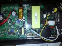
The capacitors right next to rectifier rated 200v are showing 166v on multimeter. Is that the starting point in the circuit?
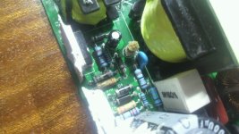
yes, the 166V is the rectified RMS voltage output from the bridge. it is DC voltage, charge stored on the capacitors that is then pushed through the transformer at high frequency, to induce current to flow in the secondary windings of the transformer, and that secondary winding is what is connected to the back end through those 5-6 legs soldered on the output of the transformer.
several things can go wrong here. the switching transistor that pushes the current into the transformer can be bad, or the feedback circuit to the front end from the back end can be defective and not force the transistors in the front to switch.
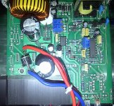
in the back end the ground is negative and should be easy to find running from the transformer to the output wire. the big toroid in the middle of the current flowing to the back end helps reduce the voltage spikes in the back end as the current pulses come out of the transformer, then go through those diodes in the top of the picture and out through that big wire loop, which is called the shunt, to the positive output of the charger. the little black IC next to it, i think it has LM355 on it, is where the op amps live that tell the charger whether it should be running or not depending on the output voltage. those little blue trimpots next to the op amp help make the final adjustment of the voltage that turns on the front end, and the fan, and the other op amp in that package knows when there is too much current flowing through the shunt when the delta voltage drop across the shunt climbs above the set point, which is set by the other trim pot. so follow the traces for those and maybe you get some idea of which traces go to which function. those op amps drive the leds too, but not the same op amp usually.
so you should be able to find the output voltage across the diodes, all the way back to across the output cap. if you don't have voltage on the two traces coming off the diodes, they could be toasted.
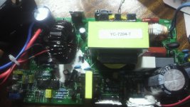
the TL494 is the controller IC for the feedback from the back end to the front end. i am no so familiar with this older type, learned more about the newer integrated chargers myself. but one of the aussie guys knows them fairly well and may have some ideas too. this is essentially a self teaching thread, blind leading the blind sorta thing, so any help is appreciated.

")