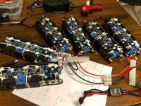
Can we parallel BMSs to handle high current ?

ichiban

100 W
Joined
Aug 19, 2018
Messages
197
Location
Bangkok, Thailand
Let's say if we need to make a replacement lithium battery pack for existing lead-acid, mid-size 1.5-ton forklift (48V, 450Ah or more) then we will need a high current BMS to take care of our batt pack. Since high current BMS is harder to find, fewer choices, and might be at risk if we depend only on a single BMS for the whole big pack. Of course, 1 BMS is easier to handle, lower cost and all that. But, since there are plenty of smaller 100-200 Amp BMSs available in the market, it might be more versatile to put multiple batt modules together with multiple BMSs to handle the job.

Existing system : 1.5-ton forklift
Working Ah for an average mid-size forklift =
430A max for drive motor (with brake fully engaged), and,
250A max for lift motor (with brake fully engaged = max load to lift)
Max of the max = 430A+250A = 680A but this figure rarely occurs.
Standard deep-discharge lead-acid batt pack = 48V, 435Ah (5hrs).
I would assume that max current is 600A. Average working current is 300-400A.

So, a BMS or BMSs capable of handling 800-Amp is considered.

I am thinking of ...

Single line diagrams form for ease :


ATTACH]


Per diagram #1) Modular battery system : Cells and BMSs together are pre-fab as a module. Common BMSs outputs, common charge ports are to be connected once a module is plugged to the system.
By doing this, modules (with BMSs) can be easily added to expand capacities. Different capacity (Ah) of modules can be mixed. Higher cost and complexity from extra BMS, wires & connections.

Per diagram #2) Single BMS / multiple batts modules : Simpler, but limited by capacity of the single BMS. Each serial groups of all the packs are connected. For examples, 1S of module 1, 2, 3, and ... are connected. 2S of module 1, 2, 3, and ... are connected. and vice versa. Voltage of each serial group and the whole module must be very close before plugging in a new module. All

Each module : IMO should be 40-50Ah / module nominal

Depending on cells type, capacities, chemistry and etc., expected size of each module is

For cylindrical cells :
14S10P (cylindrical Li-Ion, from 18650 & up) - lots of spot-welds to make, OR
15S or 16S10P (cylindrical LiFePO4 from 18650 & up) - also lots of spot-welds to make.

OR
For prismatic cells :
15S or 16S2P or 16S4P (prismatic LiFePO4, 240Ah or 120Ah cells) - easy to assemble but less energy density, higher cost.

Bluetooth connections :
It is nice to have a remote acquisition of batt modules/pack status. But I seriously prefer a much longer monitoring range than that 5 to 10-meter range of bluetooth. It bothers me every time when I want to check my e-bike pack status that I have to walk up to the bike. Via IP ?

Charger :
In this particular circumstance, a power charger is needed, something starting at 10-20kW, 48V, CC-CV to charge all of the modules at once via BMS(s). May be 200 to 400-Amp charging current. I think it is better this way than using smaller chargers to charge individual modules.

Questions :

1) What would the expert say about above designs for both diagram #1 and #2 ?

2) What are the downsides of each design, if any ?

3) What is the max number of BMSs that can be paralleled ? Only applicable to diagram #1.

4) How many bluetooth connections can we connect to a single user device ? Let's say that we have 12 batt modules (with 12 BMSs) connected together to make a batt pack. Will all of the BMSs be able to connect and display each individual module status simultaneously ? This might be a drawback, since we have to sum-up all of each module data to obtain the whole pack working log. Is there any easy way to combine them altogether to get 1 complete report ?

5) Any longer range batt pack status monitoring system ? For me, bluetooth is too limited. Anyone know/experience of any internet-based monitoring system ?

6) By using 1 big charger to charge all of the modules at once, some module might be charged faster than others. Voltage of each serial group (or whole module) can be different. Can different % SOC modules be plugged-in together, for both diagram 1 and diagram 2 ? This is to rest assure that risk is not there for us to take. Is it safer by design of the system ?

7) OR some more appropriate designs might be better/safer than #1 & #2 above ?

Any productive comments from anyone are welcome and appreciated.
 
If the BMS is well-designed, and takes the idea of paralleling into consideration, you might be able to safely do so.

If it doesn't, then if one BMS shuts down and another doesn't, or has a delay, now it's handling all the current, and if it can't handle the full current flowing at that time, it'll fail.

Since FETs tend to fail shorted, then current may still continue to flow (perhaps at a reduced rate, depending on how it fails), and the battery (which the BMS was trying to protect) is now unprotected, and will continue to discharge, damaging cells, etc.


I'd recommend using a single contactor instead, triggered by the BMS's FET control lines. You'll probably have to build a bit of electronics to drive the contactor coil from the FETs.
 
amberwolf said:
If the BMS is well-designed, and takes the idea of paralleling into consideration
Recommendations, links for any that do?

Otherwise it seems, ignore the current rating, focus on the features & quality aspects aside from the FETs,

adapt to using external contactors so the power current does not even flow through the BMS, use it to protect based on voltage only.

Is that right?

Could still use two (sets of) contactors though with a separate-port BMS right?

One to cut charge sources based on HV, the other cutting loads based on LV. . .

Correct?
 
ichiban said:
Questions :

1) What would the expert say about above designs for both diagram #1 and #2 ?

2) What are the downsides of each design, if any ?

3) What is the max number of BMSs that can be paralleled ? Only applicable to diagram #1.

4) How many bluetooth connections can we connect to a single user device ? Let's say that we have 12 batt modules (with 12 BMSs) connected together to make a batt pack. Will all of the BMSs be able to connect and display each individual module status simultaneously ? This might be a drawback, since we have to sum-up all of each module data to obtain the whole pack working log. Is there any easy way to combine them altogether to get 1 complete report ?

5) Any longer range batt pack status monitoring system ? For me, bluetooth is too limited. Anyone know/experience of any internet-based monitoring system ?

6) By using 1 big charger to charge all of the modules at once, some module might be charged faster than others. Voltage of each serial group (or whole module) can be different. Can different % SOC modules be plugged-in together, for both diagram 1 and diagram 2 ? This is to rest assure that risk is not there for us to take. Is it safer by design of the system ?

7) OR some more appropriate designs might be better/safer than #1 & #2 above ?

Any productive comments from anyone are welcome and appreciated.

#2 is not possible, unless the modules were unified into one big one.

The BMS has to connect to each series cell connection in order to actually do its job. So if you have 3 modules and want to use 1 BMS, all the modules would have to be connected at the cell level. Effectively making them 1 big module...

It is far more effective to just use 1 big reliable BMS though, so if you unify the modules into one battery, you could use one of these:

https://energusps.com/shop/product/tiny-bms-s516-150a-750a-36

Configurable for 4-16S, built in support for an external contactor, as big as you need, and can handle up to a 750A with external hall effect sensor. Also can connect through USB/UART so you can connect it to a computer, a ZigBee, whatever has USB or UART. Which would allow you to record/share the data through wifi/4G/900Mhz, etc.
 
Thanks for the comments : amberwolf, john61ct, MAXIMUM_AMPS

All I want from this design is to have the liberty to add or remove lithium modules from the main pack and utilise its versatility by design. There are some applications that will benefit from that, and, lead-acid can hardly offer that flexibility, if even possible at all.


amberwolf said:
If the BMS is well-designed, and takes the idea of paralleling into consideration, you might be able to safely do so.

If it doesn't, then if one BMS shuts down and another doesn't, or has a delay, now it's handling all the current, and if it can't handle the full current flowing at that time, it'll fail.

Since FETs tend to fail shorted, then current may still continue to flow (perhaps at a reduced rate, depending on how it fails), and the battery (which the BMS was trying to protect) is now unprotected, and will continue to discharge, damaging cells, etc.


I'd recommend using a single contactor instead, triggered by the BMS's FET control lines. You'll probably have to build a bit of electronics to drive the contactor coil from the FETs.


So, amberwolf, I understand that you imply that it is risky to follow diagram #1 : Modular battery system : Cells and BMSs together are pre-fab as a module and have multiple modules in parallel. Since we do not know how the particular BMS are designed, and there it takes only a single few-second incident to short circuit an ON and an OFF FETs and can cause serious short-circuit accident.

For higher current requirement, I assume you refer also to external solid state relay ? Which is fast, no machanical moving parts and last a long time than mechanical ones.
 
MAXIMUM_AMPS said:
#2 is not possible, unless the modules were unified into one big one.

The BMS has to connect to each series cell connection in order to actually do its job. So if you have 3 modules and want to use 1 BMS, all the modules would have to be connected at the cell level. Effectively making them 1 big module...

It is far more effective to just use 1 big reliable BMS though, so if you unify the modules into one battery, you could use one of these:

https://energusps.com/shop/product/tiny-bms-s516-150a-750a-36

Configurable for 4-16S, built in support for an external contactor, as big as you need, and can handle up to a 750A with external hall effect sensor. Also can connect through USB/UART so you can connect it to a computer, a ZigBee, whatever has USB or UART. Which would allow you to record/share the data through wifi/4G/900Mhz, etc.


How about balancing circuit (bleeding) ? For e-bike scale (sub +/- 1-kW ) , low bleeding current ( around 100 mA) should be fine. Normal heat dissipating R should do the job.
But for > 10-20kW pack, I think we might need active bleeding for higher current ? I assume 2-3 Amp or more should be appropriate ?


I might have confused you guys by not having clearly explained the diagrams. I added some detail into the old one. My "sense" wires are "balance wires" which make every module connected to cell level when we plug-in a new module.
If that is the case, diagram # 2 should be OK to go for the sake of flexibility to add/remove some modules ? Any other drawbacks that I might overlook ?

Another aspect before proceed, I think there should be some kind of electronics usage log permanently attached/installed to each module to keep permanent record - just like the odometer in your car. And also type of cells to be connected together should be the same or at least very similar . Same age & same type of cells to be connected together. In this case, diagram #1) Modular battery system : Cells and BMSs together should be better.
So there must be a sweet spot for the final design - all of the good / none of the bad (or very little ).

I will contact energusps and see if they have something to answer my questions. Thanks MAXIMUM_AMPS for the recommendation.

I might really go for the real project soon, if everything is OK.
 
ichiban said:
All I want from this design is to have the liberty to add or remove lithium modules from the main pack and utilise its versatility by design. There are some applications that will benefit from that, and, lead-acid can hardly offer that flexibility, if even possible at all.
Actually the fact that lead uses no BMS makes it much easier to make things modular, add / remove, reconfigure.

Using relays to switch between 12V and 24V configuration is bog standard in trucking and racing circles for example.

Not relevant to your overall scheme, just sayin. . .
 
john61ct said:
ichiban said:
All I want from this design is to have the liberty to add or remove lithium modules from the main pack and utilise its versatility by design. There are some applications that will benefit from that, and, lead-acid can hardly offer that flexibility, if even possible at all.
Actually the fact that lead uses no BMS makes it much easier to make things modular, add / remove, reconfigure.

Using relays to switch between 12V and 24V configuration is bog standard in trucking and racing circles for example.

Not relevant to your overall scheme, just sayin. . .


Thanks john61ct.

Your comment is very interesting !! :wink: :wink:

But I prefer BMS to make me sleep better at night for the pack I design for someone who know very little about lithium batteries.

:) :)
 
ichiban said:
My "sense" wires are "balance wires" which make every module connected to cell level when we plug-in a new module.
If that's the case then I believe one BMS will do, but **for cell level voltage** issues only.

Apparently does not matter if the "modules" are connected to each other **at their pack-level voltage** in parallel or in series.

But if in series, you still need current protection, and overall bank-level HVC/OVC handled by different separate devices.

These surmises were not explicitly endorsed here: https://endless-sphere.com/forums/viewtopic.php?p=1514687#p1514687

so consider them speculative.

A much more detailed diagram of just the connections relevant to this specific topic would be helpful if you want to pursue it.
 
That thread is already on my read list queue.

I will have to go out do things and come back to read it.

I really love ES for the endless knowledge it always provides.

I soon will have to do some maintenance for my Bafang BBSHD 6000+km & 14S5P LG MJ1 and I will keep ES posted for the benefit of the community. There will be some upgrades / tweaks from real-life uses too.
 
ichiban said:
For higher current requirement, I assume you refer also to external solid state relay ? Which is fast, no machanical moving parts and last a long time than mechanical ones.

No, when I said contactor, I meant contactor, which is a mechanical disconnect (usually a form of relay, but often sealed and good ones are also filled with inert gas to minimize damage from plasma arcing during disconnect-under-load, and may alos have magnetic helpers to extinguish arcs like good DC breakers do).

SSRs are still semiconductors, and may still have the same failure mode as FETs. If that happens, the battery that was supposed to disconnect won't, and will still continue draining, whatever problem it has. You also wont' even know that it's still on and being damaged, unless you have something to tell you that. (a failsafe warning circuit to detect if it's still got current flowing).

Contactors can *also* fail shorted, but if properly designed and sized, it's rare. Usually it happens when it's not really capable of breaking the circuit under the conditions it's being used under--it works most of the time, but eventually something happens.... YOu'd also need something to detect current flow as a failsafe warning circuit for this case, too, but it's much less of a risk.

SSRs and other semiconductor stuff does have advantages, such as no arcing, no wear and tear, etc., but their common failure mode is worrisome (to me at least).
 
Since this thread is already here I figured I'd piggyback onto it with a similar question. I bought 6 10s 5ah scooter packs all with their own BMS's. The BMS boards are nice and tidy and have temp sensing and status LEDs. They are pretty nice other than the low discharge limit of 7amps per.

If I were to solder discharge leads directly to the tin strips before the BMS could I use the original amp limited discharge leads run through a voltage scaling circuit such that the voltage is 1/10 the actual voltage? Then I could run each pack's 3.7v signal through cheap lipo alarms so if any of the 6 BMS faulted for any reason I'd have an alarm. Seems like a cheap way to get literal cell level monitoring. Is such a voltage scaling circuit easy to build or is this a lot of trouble to save the free BMS units I don't even really want?
 
DanGT86 said:
If I were to solder discharge leads directly to the tin strips before the BMS could I use the original amp limited discharge leads run through a voltage scaling circuit such that the voltage is 1/10 the actual voltage? Then I could run each pack's 3.7v signal through cheap lipo alarms so if any of the 6 BMS faulted for any reason I'd have an alarm. Seems like a cheap way to get literal cell level monitoring. Is such a voltage scaling circuit easy to build or is this a lot of trouble to save the free BMS units I don't even really want?
You can do one monitor per cell. But you can't divide by 10 at the output and trace that back to the cell. You will then get an average, not a cell by cell measurement.

In your example you can just parallel all the packs and have it work. If a BMS shuts down it will simply disconnect that battery from the circuit.
 
My goal is to bypass the BMSs such that they cant actually shut off the packs. I need higher discharge rates than they allow but wouldnt mind using them as warning lights.

The voltage scaling circuit would ideally take the main pack voltage and turn it into a signal that a cheap 3$ lipo alarm could use. So if a pack tripped I was thinking the lipo alarm would register an open and sound.

What I dont know is if the discharge leads would actually read as an open when the packs are paralleled. Im thinking they probably wouldnt but instead would just be at the same voltage as the other packs in parallel. Perhaps I could isolate them with diodes so im only reading each pack?

Perhaps a better way to do this is to figure out what drives the Mosfet that shuts the bms down or try and use the signal that changes the led color on the bms. It goes red under fault and stays blue normally. That should be a different voltage causing that color change right?

Its probably a bit of trouble to set up. Just seemed like a waste to cut 6 bms off when they are already installed cleanly. An added benefit was that any cell problem would be identified specifically rather than the other parallel cells in its group covering for it.
 
DanGT86 said:
An added benefit was that any cell problem would be identified specifically rather than the other parallel cells in its group covering for it.
That is only possible when the cell is no longer paralleled to the group.

I think you need to study more how BMS function.

What functionality do you want from a BMS, and at what stage of the pack's cycling? Could just plug the BMS in when you need it.

Build your pack so it is easily removed.

If it is of good enough quality, you very likely can operate (discharge) without it just fine.

RC type balancing chargers also do a great job.
 
DanGT86 said:
My goal is to bypass the BMSs such that they cant actually shut off the packs. I need higher discharge rates than they allow but wouldnt mind using them as warning lights.
1) Paralleling them reduces the current each one supplies. So you will get the higher discharge rates.
2) If you still don't like this you can disable the disconnect (usually FET based) and wire-OR them all into a contactor. This will then then trip when any one of the BMSes sees an overcurrent. You will get somewhat less than the sum of all the current limits.
The voltage scaling circuit would ideally take the main pack voltage and turn it into a signal that a cheap 3$ lipo alarm could use. So if a pack tripped I was thinking the lipo alarm would register an open and sound.
Won't work.
Perhaps a better way to do this is to figure out what drives the Mosfet that shuts the bms down or try and use the signal that changes the led color on the bms.
Yes, that is #2 above.
Its probably a bit of trouble to set up. Just seemed like a waste to cut 6 bms off when they are already installed cleanly. An added benefit was that any cell problem would be identified specifically rather than the other parallel cells in its group covering for it.
You don't need to cut any BMSes off. You can parallel the packs.
 
Thanks for the guidance guys.

My main motivations here were:
  • Retaining the balance function when bulk charging
  • bypassing the main discharge cutoff to avoid the 1.5c rate limit of these BMS units

The added bonus benefits to the complex solution I have been asking about here are:
  • Being lazy not wanting to cut off 6 BMS boards as they are attached to the nickel strips welded to the cells
  • Being cheap not wanting to spend money on a fancy BMS when I have 6 cheap ones here
  • Getting a bit more specific information about possible problem cells by deliberately not paralleling each cell between packs
  • getting the temperature sensing function via the sensors glued onto the packs already

So basically the normal sensing functions of the BMSs would be present but they would no longer have the ability to control the actual pack output. From years of reading on the forum I get the impression its usually better to parallel all cells in a series group. That's what I have always done in the past with lipo and I balance charge every few cycles and use cheap alarms while riding. I bought these packs super cheap and when they came with free BMS units that were nestled in the plastic cell holders I started thinking it might be nice to leave them.

I understand the Fet signal would be the most logical place to drive a warning light/alarm from but I have no idea how to build a circuit to do that. Perhaps de-soldering the status/fault led and extending it with wires would be the best compromise.

I'll probably just bypass the discharge output by going straight to the nickel strip and parallel all 6 cells in each group across packs but leave the BMS units attached to retain their balance function. If I ever want to figure out a fancy circuit to tap the Fet driver signal I suppose than I'll be glad I didn't cut them off.

scooter 2.jpg
 
I, at one time had a few hundred two cell packs. Each pack was 7.2 volts at 2200ah with its own BMS. I parallel these in groups of 6 then built 2 separate 6s packs. I charged them in parallel then used them in series as a 12s 12p battery.
This worked out well for quite some time until I discharged it low enough for one of the BMS's to shut down. The result was a cascading failure as each shutdown increased the current for the ones remaining.
A subsequent autopsy revealed that most of the protection boards were permanently shut down.
The short answer is that paralleling BMS's works fine, until there is a fault.
 
DanGT86 said:
My main motivations here were:


The added bonus benefits to the complex solution I have been asking about here are:
Listy bits invisible from here

 
Hwy89 said:
I, at one time had a few hundred two cell packs. Each pack was 7.2 volts at 2200ah with its own BMS. I parallel these in groups of 6 then built 2 separate 6s packs. I charged them in parallel then used them in series as a 12s 12p battery.
This worked out well for quite some time until I discharged it low enough for one of the BMS's to shut down. The result was a cascading failure as each shutdown increased the current for the ones remaining.
A subsequent autopsy revealed that most of the protection boards were permanently shut down.
The short answer is that paralleling BMS's works fine, until there is a fault.

I figured the cascade failure would result from discharging through the output terminals of the bms which is why I wanted to bypass them and only use their open/closed state for a warning.
 
Back
Top