Cell-level Fusing

titusmc

100 W
Joined
Sep 30, 2015
Messages
112
Location
Troy, New York
Hi ES,

I've been in the process of building five 14S8P 18650 packs over the last few months (whenever I have time) and it's made me think a bit about fusing. This video by 15-sec-of Fame https://youtu.be/5EE4TsuzD_Q convinced me to build one pack using PTC fuses (4A) at the cell level. The argument for the fuses, as I understand it, seems to be that if a cell internally shorts the fuse will prevent the other cells in the parallel group from dumping lots of current through the shorted cell, thereby avoiding a fire.

Here's my most recent build featuring these PTC fuses.
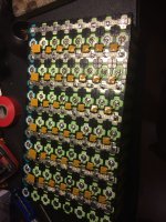
IMG_0803.jpg

Doing this is kind of a pain, since it requires lots of very careful positioning of the fuses, anchoring with tape, and careful soldering. That's why I'm questioning it - I can certainly make packs faster if I just use tinned copper braid for all connections.

It seems like almost no one does this cell-level fusing on ebike packs, commercial or DIY, so the question I have is - is this overkill for safety? I certainly don't want a fire, but I also feel like the risk of having one this way is extremely low (with no real data to back that feeling up). Does anyone know more about this type of failure mode - that is, parallel cells dumping current through an internally shorted cell? Will a 4A PTC fuse actually help or could <4A through a shorted cell still result in a fire?

Side note: I have been using an 80W Weller chisel-tip iron from amazon and it is amazing for soldering cells quickly. I just tinned both terminals of 112 cells and added bus bars on the negative of each parallel group in about 2 hours. My contact between cell and iron only lasts about 5-10 seconds at most with the 80W Weller.
 
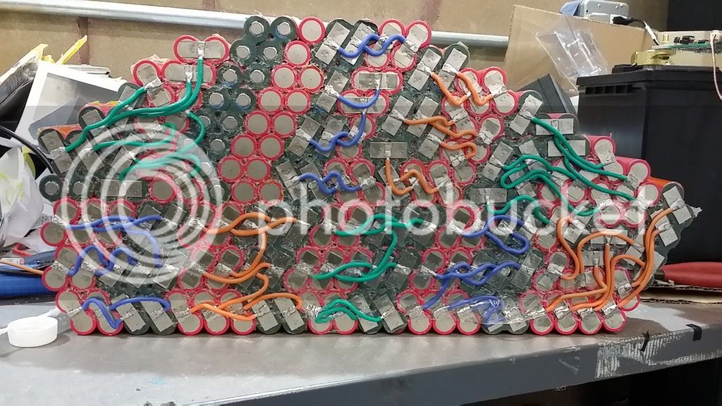
I feel your pain. I decided to use wires to connect my pack in series, and I think you may be the only one who understands how tedious the job is. Just take a look at my pack here, it may make you feel better.

I don't think it is worth what you are doing to be honest. I would have put more time in securing the pack and making sure it is secure. But I keep my bike in the garage and have a steel enclosed frame, so there is no worry if the pack goes on fire.

If your pack is secure the odds of having it go on fire are so slim.

I also have heard soldering like you are doing can be bad. 5-10 seconds is way too long with a 80 watt iron. When i soldered my heated clothing 18650 cells I just touched the cell for no more than 3 seconds max. But it is probably debatable if it would do any damage.

On my pack I soldered my wires first to the nickel tabs, and then welded them on. This way no heating of the cells. Every two cells are in parallel, and I'll add a small nickel tab to put the rest into parallel. You should have done something like that and fused every two cells in the center. This way the current is distributed evenly and no soldering to the cells.

 
Offroader said:
5-10 seconds is way too long with a 80 watt iron. When i soldered my heated clothing 18650 cells I just touched the cell for no more than 3 seconds max. But it is probably debatable if it would do any damage.

I said 5-10 seconds, but it is usually closer to the low end - 5 seconds, sometimes as little as 2-3 secs depending. Some cells have terminals that need up to 10 seconds before the solder wets nicely. I've never done any testing to see if this actually "damages" the cells, but I may do so in the future. What is the expected impact of soldering heat? Lower capacity?
 
How are you going to put your cells in parallel?

I believe it is capacity loss, but capacity loss goes hand in hand with all the other cell losses, like more voltage sag, less amp output from the cells.

It seems universally accepted that you shouldn't solder to the cells and many companies even sell cells with tabs welded on so you don't have to solder directly to the cell. I would like to see an actual study to see just how much it impacts cell life.
 
I'm going similar to Tesla style, using 0.1mmx1mm nickel plated steel as fuse.
Trips about 12A. In case if cell shorted or something else comes wrong.
HV8un1b.jpg
 
DVDRW, that is actually what I intend to do when I parallel my cells.

This will limit a short to only two parallel cells if something happens to my pack, instead of pulling from all 14 cells.

how did you determine it trips at 12 amps?
 
titusmc said:
Here's my most recent build featuring these PTC fuses.
This is a very nice pack, but unfortunately PTC fuses never stop conducting, they just raise their resistance considerably in over current condition and heat from current flow holds them in this high R state until you reset it by disconnecting power source. I can imagine several failure scenarios with a fire ball as result, example:
1 Cell shorts internally and discharges the whole P group to 0V (it may take a while but it is inevitable by PTC fuse principle), then you start discharge cycle and reverse-charge the dead cell group.
Basically you are saving the fireball for later :D , unless you have some kind of protection system or protocol.
P.S.The parallel cell group will be dead in any case.
 
Really nice battery pack. I've actually been trying to figure out the same thing after watching 15-sec-of Fame. My question is more aligned to how to even determine the size of the fuse, and if PTC fuses are even the way to go amongst fuses. Here are some of the questions that have me completely stumbled...and maybe somebody else too.

1) Why do the 16v 4A fuses even work? (Don't you need to be able to withstand the entire current of 48v for example?)
2) Would 30v 4A PTC fuses work just as well as the 16v 4A fuses? (http://www.ebay.com/itm/-/231815281043?roken=cUgayN&soutkn=J5okXK)
3) Why are 16v 4A fuses even the right ones? (How is this determined; probably related to previous questions)
4) Are PTC fuses the best type of fuse for this application? (fast vs slow; inrush current; etc.)

This has been really eating away at me for some time now, and I feel that I get more questions than answers as I do more research. I'm hoping this is a good thing. To be fair, I've asked 15-sec-of Fame in the comment section of this video(https://youtu.be/cDmo2rt1ThM), and he gave me an excellent response. Also, I brought this up on the Electrical Engineering Stack Exchange forum, and I've also received some really good feedback. In that one, I actually made a diagram of the battery I'm looking to assemble (http://electronics.stackexchange.com/questions/226493/using-fuses-to-connect-batteries-in-series).

I really appreciate any further insight and discussion into this.
 
2alexsky said:
Really nice battery pack. I've actually been trying to figure out the same thing after watching 15-sec-of Fame. My question is more aligned to how to even determine the size of the fuse, and if PTC fuses are even the way to go amongst fuses. Here are some of the questions that have me completely stumbled...and maybe somebody else too.

1) Why do the 16v 4A fuses even work? (Don't you need to be able to withstand the entire current of 48v for example?)
2) Would 30v 4A PTC fuses work just as well as the 16v 4A fuses? (http://www.ebay.com/itm/-/231815281043?roken=cUgayN&soutkn=J5okXK)
3) Why are 16v 4A fuses even the right ones? (How is this determined; probably related to previous questions)
4) Are PTC fuses the best type of fuse for this application? (fast vs slow; inrush current; etc.)

This has been really eating away at me for some time now, and I feel that I get more questions than answers as I do more research. I'm hoping this is a good thing. To be fair, I've asked 15-sec-of Fame in the comment section of this video(https://youtu.be/cDmo2rt1ThM), and he gave me an excellent response. Also, I brought this up on the Electrical Engineering Stack Exchange forum, and I've also received some really good feedback. In that one, I actually made a diagram of the battery I'm looking to assemble (http://electronics.stackexchange.com/questions/226493/using-fuses-to-connect-batteries-in-series).

I really appreciate any further insight and discussion into this.

Take the example of powerlines. how do you think they can transfer the massive amounts of energy they do and still be reasonably thin?
The trick is high voltage. You do have a ceiling on how much current you can flow through a cable of a certain cross section area, but increasing the voltage enables you to still transfer more power. P=UxI
So if the fuse is a regular dumb fuse that will burn off from excessive current, then it wont care about the voltage.
 
2alexsky said:
1) Why do the 16v 4A fuses even work? (Don't you need to be able to withstand the entire current of 48v for example?)
The potential difference (voltage) between two parallel cell groups is only 4.2V max. The fuses are never going to have more than 4.2V across their leads.
2alexsky said:
2) Would 30v 4A PTC fuses work just as well as the 16v 4A fuses? (http://www.ebay.com/itm/-/231815281043?roken=cUgayN&soutkn=J5okXK)
Probably, however I'm not very familiar with PTC fuses so someone else might be able to give a better answer.
2alexsky said:
3) Why are 16v 4A fuses even the right ones? (How is this determined; probably related to previous questions)
The 4A will be a bit more than each cell can handle. Not too low or it could trip on short high current peaks. Not too high or the batteries may never be able to give enough current to trip it.
2alexsky said:
4) Are PTC fuses the best type of fuse for this application? (fast vs slow; inrush current; etc.)
I think a standard slow blow fuse (1 per parallel cell) would be better as it will stop conducting entirely when it blows and will not reset.

Of course a pack where each cell is individually fused would be best but that's much harder.

The reason there are multiple fuses rather than one big one are that so current flows equally from each cell in the parallel string. If there was just one big fuse in the center, the middle battery would be providing the most current and the batteries at the edge of the pack would be providing a lot less because of the voltage drop over the nickel.
 
DVDRW said:
I'm going similar to Tesla style, using 0.1mmx1mm nickel plated steel as fuse.
Trips about 12A. In case if cell shorted or something else comes wrong.
HV8un1b.jpg

Very impressive. Had considered this a while ago, but far, far too lazy to actually do it :lol:
 
Noob question here (but I'm considering more and more building my batt, thanks to you Offroader) : does a fuse convert some of the current (even when not pushed to its limits) as heat and does it has an impact on performance?
I remember a youtube video of a guy saying something along those lines...

Envoyé de mon XT1092 en utilisant Tapatalk
 
TheBMallory said:
Noob question here (but I'm considering more and more building my batt, thanks to you Offroader) : does a fuse convert some of the current (even when not pushed to its limits) as heat and does it has an impact on performance?
I remember a youtube video of a guy saying something along those lines...

Envoyé de mon XT1092 en utilisant Tapatalk

Yes, it does convert the current to heat but the fuse should be as short as possible so it has a minimal effect on performance.
 
parabellum said:
Basically you are saving the fireball for later :D , unless you have some kind of protection system or protocol.

I forgot to mention that I use a SuPower Battery balancing BMS on each pack I build. They seem to work very well, but they are somewhat expensive ($49.99 for 14S 45A).

Also, thanks to everyone who has complimented my build quality - it means a lot to me.

For those looking carefully, the string of teal cells are Samsung 20Q for high current scenarios (acceleration, short hills) and these have 8A PTC fuses. The rest of the cells are tested and matched recycled laptop cells - I rewrap them in green PVC heat shrink so it looks more appealing. The laptop cells all have 4A PTC fuses. I chose these values by assuming that the 20Q's had 1/3 the DCIR of the laptop cells have therefore would supply 3 times more current under load. The controller is 20A, which gives:

A = current per 20Q
B = current per laptop cell

A = 3*B
1*A+7*B = 20 amps

So, under max load..
B = 2 amps -> 4A fuse
A = 6 amps -> 8A fuse

I have 5 20Ah 52V packs ready to be soldered up...
5packs.jpg
 
Solarpower said:
Nice! What are you gonna use the packs for? A lot of ebike riding since you got 5 of them? :D

Pretty much - I'm planning to do a 95-mile ride this summer on a single charge, so I'd be carrying at least 3 of these packs with me.

Longer term, I want to set up a solar charging system for the packs that will function as both my normal charger for commuting and an emergency backup power system. Those 5 batteries are each roughly 1 kWh, and I have cells to make another 3 packs, for an eventual total of 8 kWh - majority of cells recycled, with about 2.5 kWh being new cells (a mix of Panasonic NCR18650BF, LG HE4, LG HG2, and Samsung 20Q).
 
Looks like you some of you guys are putting your cells really close to each other instead of using cell holders. The entire can is a negative terminal, covered in a thin layer of plastic - chafe through that plastic, or split it with an impact from dropping it, you can have a short between the cans. Best case they drain down and vent, worst case fire, seen a few suspected cases of that reported here over the years. Doesn't matter on parallel cells, but hopefully there is at least some kapton tape between series cell groups.

The heat from soldering ages the cells, offroader's approach of soldering to the tabs before spot welding is the way to go. :D Also, as zip points out if you melt the vent on the positive end closed, you can have an overpressure event.

-JD
 
They can use a high temp seal, but as I think LFP says not good to heat electrolyte or the seal on top and make it burst with it's guts. Without Sweet smelling electrolytes. What is that smell. You ever smell that. ? Boiling bubbles.
 
titusmc said:
Hi ES,

I've been in the process of building five 14S8P 18650 packs over the last few months (whenever I have time) and it's made me think a bit about fusing. This video by 15-sec-of Fame https://youtu.be/5EE4TsuzD_Q convinced me to build one pack using PTC fuses (4A) at the cell level. The argument for the fuses, as I understand it, seems to be that if a cell internally shorts the fuse will prevent the other cells in the parallel group from dumping lots of current through the shorted cell, thereby avoiding a fire.
I am a bit surprised when I see packs like that built as safety conscious with "fuses etc" because if there trying to prevent the entire pack going off then glueing the 18650 cells so close together will most certainly cause a chain reaction for all of them to go off as shown by Justin Lees video in URL below here.. He actually added a fair amount of distance between each cell and they still almost all went off..

There is absolutely no hope for that pack in that youtube video above to not go off entirely if "one" cell goes off and I find it pretty disturbing it got over 6000+ views and alot of thumbs up on top of it being titled "How to build a 48v e-bike battery" it really should be the exact opposite if its about safety.. no argument.

As mentioned in the youtube grintech description the heat went beyond the FLIRs sensor limits of 150 degrees Celsius so they don't know how hot it got.. If folks are building packs with dodgey untested glue/other materials that can easily burst into flames when hot then adding fuses might be giving a false sense of security.

I mishandled a Samsung 18650 while experimenting with a battery pack build and one of the cells glowed lava orange hot for a good 30 seconds...
https://endless-sphere.com/forums/viewtopic.php?f=14&t=71125&start=25#p1082608
https://www.youtube.com/watch?v=oBlac5gWLfI
 
Would anyone know, while building my pack I accidentally shorted a couple of cells to another parallel adjacent group with the nickel tab.
It was for a fraction of a second but caused a spark and a little burn mark on the nickel and a tiny burr on the battery.

I believe it wasn't that bad because it was only an adjacent parallel group and for a fraction of a second, but who knows.

Do these kind of fraction of a second shorts do serious damage to the cells? Since the batteries are limited to such low charge amps, I must have charged the cell at a super high rate.
 
999zip999 said:
Still can't see parallel connects ?

The fuses are conductive, so the parallels are the negative bus bars (tinned copper braid). For the pack positive terminal I also added a bus bar this mid-build image doesn't show.
 
Back
Top