Cheap Single Cell Charger / LED Driver

fechter

Administrator
Staff member
Joined
Dec 31, 2006
Messages
16,566
Location
California Bay Area, USA
I got a few of these CC/CV switching regulators off eBay.
The one I got is: http://www.ebay.com/itm/400440730939?ssPageName=STRK:MEWNX:IT&_trksid=p3984.m1497.l2649
Or you can search for "LM2596 DC-DC Step-down Adjustable CC/CV" and find several.

I got 3 for about $10 shipped. I can't even buy the parts for that cheap.

Input can be up to 35V. 3A maximum output. Voltage and current are individually adjustable by pots, and there's a third pot that you can adjust the trigger point for the indicator LED. Normally you'd adjust this for something like 10% of the CC level to tell you when the cell has finished charging.

I can power it with any of several old laptop power supplies or wall warts I have in my junk box.

I orginally got it as a LED driver for some 3W LEDs I found. It works great for this too. I dialed in the current I wanted and it stays there over a wide range of input voltage. At 1A, it barely gets warm and I don't think it would need a heat sink. For 3A, it will need some kind of heat sink.

I quickly figured out this is the ideal gadget for charging single cells in a pack to balance them. I also have a LED light that runs off a 1S, 12P Li-ion pack and I can use it to charge that thing.

The instructions kind of suck, but easy enough to figure things out. Below is a picture showing the locations of the adjustments.
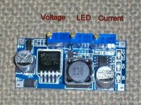
100_0435.jpg

When it's running in the CC mode, the red (CC/CV) LED comes on (hard to see LEDs in the picutres)

When the current drops below the CC set point, the blue (CH) LED comes on and the (CC/CV) LED goes out.
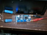
100_0430.jpg

When the current gets below the point you've dialed in on the middle pot, the blue LED goes out and there's one remaining red (OK) LED lit on the other side, indicating the charge is complete.
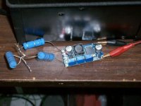
100_0433.jpg
 
Cool!!!

I have a bunch of those laying around for LED light projects I never got around to... I often wondered in passing if they would work as chargers, but never pursued it.
 
Just bought a couple will be useful to rebalance my idle lipo pack, searched other items from that eBay link too, there was a digital version with spi rx and tx which did 5amps was 3 times the price however. Thanks for the heads up fechter
 
RLT said:
Cool!!!

I have a bunch of those laying around for LED light projects I never got around to... I often wondered in passing if they would work as chargers, but never pursued it.
They do. I use them 3 years for, only drawback, output is not isolated from input, only 1 can be used in same string with same source.
 
i have been thinking it would be possible to use a DC convertor to push charge into one cell of a battery that had lower capacity than the others in order to do dynamic balancing of a lifepo4 pack during discharge.

if the ground has to be shared between input and output then i could only use the section of the battery above the low capacity cell to push current to it.

i may try that with these and adjust the current so that the amount of charge delivered during the time the battery was going from full charge to full discharge on this cell is equal to the difference of the capacity of the cell that is missing compared to the next lowest capacity cell and that charge would be injected by the DC convertor.

also the 2nd lowest may be capable of this kinda dynamic balancing without interfering with the first, and the second could also be pushed up as the entire battery is discharged. so get that extra 5-8% out of the battery. for little cost.

just put a little DIP switch on it and turn it on when i drive and turn it off when i stop.
 
dnmun said:
i have been thinking it would be possible to use a DC convertor to push charge into one cell of a battery that had lower capacity than the others in order to do dynamic balancing of a lifepo4 pack during discharge.

I've thought of that too. I think an isolated version would be better though. Just needs a transformer.


If you wanted to charge more than one cell at a time, you could use separate wall warts for each one. Another approach would be a transformer with a bunch of separate secondary windings. The input to the board doesn't need to be regulated so something pretty crude would work.
 
yep. i have been testing the wallwarts, 120V AC adapters, but with it, i have no control over the current or output voltage. the voltage would have to be max at 3.6-3.7V and i would have to adjust the current so i only added enuff charge to the low cell to keep it off the bottom for 5% longer. that would be about 4Ah for my lifepo4 pack. so i would need about 4Ah/6hr or about 600mA.

just remembered i have one of those old octopus style lifepo4 balancing chargers for 16S that came with my ozzie 10Ah pouches. have to look at how they are isolated. that could give me 7 different current sources, if they could be isolated. then figure how to regulate current. but the voltage endpoints are set already.

but when i was doing this with the SLA packs, using a 12V power supply, an icharger with a regulated current, i ended having trouble balancing the pack when i recharged because the battery with the lower capacity would top out first and i had to use a big power resistor to drain current off that one when i recharged to prevent it from overvolting.
 
Sorry to crash in here but I am trying to find out more info on this maybe similar but larger capacity module, i wondered if anyone in the west is selling it on with more info
http://www.ebay.co.uk/itm/600W-CC-CV-12-60-12-80V-DC-Volt-Converter-LED-Driver-Regulated-Voltage-Supply-/351093294468?pt=LH_DefaultD
Basically I want to charge a string of Ni Zn (similar charge mode to Ni Cad) I need CC for set time, with a max set voltage that the string can attain (Cell temperature, another indicator of near end of charge, is also monitored, with a max leading to early charge termination) I have pieced together info on how to set up these converters to act as a charger, but none on this specific one. Initially I would be feeding input from 48V SLA, maybe later replacing the SLA with a power supply. The Ni Zn neither has nor needs a BMS to balance in series. Sadly a commercially available charger for this size of Ni Zn does not yet exist. sorry but I am only an installation electrician, not an electronics guy so a bit out of my depth. I think to retain CC the module monitors & reduces whole circuit resistance as the batt charges & it's own internal res rises, thus the voltage does not have to rise above a pre set max (a big no no with Ni Zn
 
It sounds like you might be able to use a regular lead-acid charger if you can set the voltage right.

What is the maximum voltage for a 48v Ni-Zn?

I didn't know those were still around. They had terrible cycle life from what I remember. Great at first, but dead after a few hundred cycles.
 
Hi, Fecther, sorry about the delay in replying (working away from home). I honestly thought SLA chargers were constant voltage rather than constant current, the wet cell lead acid are (as they often have an ammeter on board & you can see the amperage rate dropping off as the battery nears the end of it's charge)
I have the latest info from the cell maker in china, his algorithm or 'mold' as he calls it, is thus;

Phase 1) Constant Current @ 5A for 100 mins (in this case the maker does not set an upper voltage limit) but monitor temp & discontinue charge if cells temp = 50C
Rest for 30 mins
Phase 2) Constant Current @ 5A for 20 mins max, abort charge early if cells either reach 50 deg C or cells reach 43.12V (1.96 V per cell)

I think temp rises rapidly with voltage rise near the termination of charge, thus the charger can compensate for a string being recharged from a partial discharge (like nicad AA's in a multi charger). Also this is a fail safe if one cell shorts internally (as the pack ages & forms dendrite whiskers) & thus the whole pack otherwise cooks whilst never reaching termination voltage.

Only other info I have is here from a different company http://powergenix.com/wp-content/uploads/2014/04/pgx_8ah_prismatic_data_sheet.pdf
they put a voltage upper limit on the phase 1) charge, & then recommend CV in phase 2
Powergenix I gather are supplying Black & Decker with Ni Zn for tools.

I have been quoted 300+ cycles @ 80% D.O.D & price @ 60 to 70% of Li ion (China factory gate) while Powergenix say double SLA prices. If you compare the cost per cycle then Ni Zn equals Li ion, without the ticking two year time limit - weather the pack goes through discharges or not, without the dangers & without any BMS needed. So if you are a weekend ebiker the numbers stack up OK in theory
I was hoping to make a variable CC charger to give 4, 5, 6, or 8 amps CC @ up to 44V for the 36V nominal range that Hangzhou make & also for Powergenix/Amperex if they become available. I understand the CC is most important as the cells hate trickle charging (this encourages the dendrites to form) I have had to piece a lot together patiently asking one question at a time & cross referencing as I think a lot can be lost in translation, also the guy with english skills may not be the actual technician.
The 48 V DC input was to be a few volts above the output of the CC / CV module, as some are step down only, without precise info on this particular unit I am a bit in the dark
 
Most battery chargers are both CC and CV. At first it runs CC to limit the current to a safe level. When the battery voltage rises enough, it will switch to CV and the current will taper off.

As with most batteries, I think if you charge the NiZn cells well below the maximum current, you won't have heating issues.
 
On the ebay site I have noticed a 6th labelled up photo has appeared, this shows much inc a jumper (I think) that sets the input to 9 - 16V or if 'vacant' (ie removed?) 12 to 60V
http://www.ebay.co.uk/itm/600W-CC-CV-12-60-12-80V-DC-Volt-Converter-LED-Driver-Regulated-Voltage-Supply-/351093294468?pt=LH_DefaultD
This concurs with seller' instructions / description below??. (also seems to square with reading about other module behavior). The CC @ 5A is essential, the batt supplier says.
Also to check up re. SLA being CC, next time I recharge I will monitor the charge cycle with ammeter & shunt & see what happens (I still have SLA on a bike)
 
That one looks like it should easily handle 5A. Perhaps a bit overkill, but that will keep the heat down.
Yes, the jumper is installed if you want to run under 12v (like a car battery).

Pete1961 said:
The CC @ 5A is essential, the batt supplier says.
I would assume that going over 5A could result in damage or overheating. If you're willing to charge at a lower rate, I can't imagine running less than 5A would be a problem.
 
In the case of nickel zinc charging at a lower rate, say 2A would not be a good idea because trickle charging encourages dendrites (a sort of crystal chain) to form internally within the cell. They need to be charged hard & fast (I think NiCd were somewhat like this). Hangzhou recommend charging at 0.5C, CC. While Powergenix recommend charging at 1C, CC. Dendrite whiskers short out the cell internally if they form, hence a charge time limit & temp rise monitoring of the string as a back up to voltage rise.
 
Interesting. With Ni-Cd, dendrites are usually a problem if you trickle charge for long periods of time, like days on end.
Charging at a higher rate might create smaller grains in the plate structure which is usually better as long as the heat limitation is observed.

Creating their recommended charging protocol looks challenging. If the pack is not fully discharged, you won't necessarily know how long you need to charge it, so a timer is not good. Some kind of temperature monitoring sounds like it would really be a good idea. I know some of the RC chargers can be programmed over a wide range and have temperature sensors.
 
Thanks for the info. I now think that there has been a misunderstanding owing to translation difficulties, having studied much from other sources I believe that the correct charging algorithm would be CC @ 5A up to 1.9V per cell, followed by CV for a set time (up to 20 minutes). I think the CC phase is to limit the potential current that can flow (a bit like a choke) until the 'inflection point' occurs. This point is caused by both the batt internal res rising, & more importantly the 'back emf' of the battery rising, thus limiting current flow. At this point current must drop unless voltage increases further, (not allowable) so hence the the CV phase. I think with no timer set the CV phase could go on for virtually ever, with current dwindling to a very small level. (Dendrite problem, as you say)
I think the problem of a half discharged pack would be taken care of by a buzzer sounding once a pre determined voltage was reached (the changeover point to CV) as this point would be reached sooner in the case of a half discharged pack, the CV phase would then still have its same timescale (I think)
I will monitor temp rise as a safety measure, but think this is a crude back up compared to voltage & time in CV

My main sources of info ; http://www.cdtechno.com/pdf/ref/41_2128_0212.pdf http://batteryuniversity.com/learn/article/charging_nickel_based_batteries
http://batteryuniversity.com/learn/article/charging_nickel_metal_hydride

Negative delta V (the voltage dip occurring when a cell is nearly charged) is out because from the little info I have this does not happen with a Ni Zn cell, thus ruling out an adapted NiCd or Nimh charger, at least one with the charge terminated by this method (some have a temp probe) I wish Powergenix would reply as I only have the basic graphs to go on.
I am going to try the CC / CV module as this is adjustable. I have a couple of suitable transformers, & am going to feed the Tx output through a full bridge rectifier, should I put any kind of smoothing capacitor across the rectifier output? Am I on the right track with the above? Thanks, Pete
 
I think you have it. The CC phase is limited to some value that won't overheat the cells. Once the battery voltage rises to the CV voltage, the current will start to taper off naturally. Once the current gets close to zero, the thing is done and the charge should be terminated. Most lead-acid chargers should work for this application except you'd want to totally stop the charge current when it's done. The cheap way to do this is with a timer switch. Charging beyond full for a few hours is not likely to cause dendrites. You just don't want to 'float' charge it for weeks on end, so a timer set long enough for a full charge should keep it healthy.

Yes, you would want a large filtering capacitor if taking the output of a diode bridge. Value is not critical but bigger is better generally.
 
Hey fechter

Couple of quick questions/info if you could provide..

-could i use 24 of these for example to charge a 24s lipo pack or even at 50s a123 pack for my hybrid?
-will they work ok with handling a difference in voltage on the battery... lipos from say 2.5v - 4.20v and a123 2.0v - 3.65v ? (is there any overcurrent protection.. i wana be sure they will charge the cell regardless of soc of battery)

could i run say 50 single cell chargers off one power supply?
say 200w 12v 20amp psu for 24 single cell chargers at 1amp?
whats the max amp rating you think before a heat sink is required?.. do you know max rating the chip itself will handle?

thanks! ..i have lots of questions.. could really use em!

-steveo
 
Thanks for all help fechter, could you give me a ball park fig for the capacitor? I am thinking one from a fluorescent light, or from the input feed of a washing machine.

The only thing I have doubts about re. the SLA charger is that from memory they detect rise to a particular voltage point, they then 'set back' to a slightly lower voltage (as the green LED comes on), thus there is no more inflow until the SLA batt cools (& any gassing bubbles come off the plates), batt voltage drops back, the red LED comes back on & a second charge boost is given. If as say Powergenix recommenced charging CC to 1.9V / cell, followed by CV until a further 0.04A has passed into the cell. Unless the CV from the charger was set a greater than this 1.9V per cell then current would not pass into the cell. Or have I missed something?
I did see this charger, they do a 5A nominal 36V version (the one shown is 60v & has an adjustable trimmer pot) http://endless-sphere.com/forums/viewtopic.php?f=14&t=59549
I also had a quote from a maker offering to do 'customized chargers' - they could adapt one but wanted $500 for development, then $ 35 per charger (min order 100!!!)
No thanks. So I will use the CC/CV module & observe the actual performance of the trial pack as to temp (a max of 40C is more realistic I read), time in each mode etc.
Pity Powegenix will not at present engage as they suggest their batts for an electrically powered ride on mower, so I would imagine an ebike is practical, apart from the fact that the mower does probably one cycle per week @ 26 weeks per yr. Hence batt life would seem very acceptable in that application. What I would really like from them is a charge graph @ the 1C they suggest, showing int res, against time & also temp rise against the same. Int res is plotted on their graph but against a huge inrush current
 
Thanks for the link Fechter. Now I don't have to buy the stuff and build your cutoff switch for my solar modules. It may not be worth going all the way down to single cell balance charging, but I could with 1 module running each charger/driver.

I was waiting to prove your thing worked before sending the free panels, but this is proven and cheaper, and best of all I don't have to build it, so what voltage to you run again, so I know how many modules to send your way?

Thanks again, now I can finally start selling the solar modules I have stockpiled.

John
 
No, unfortunately these are not isolated so you would need a separate isolated DC source for each one. It could be a pretty crude source though. Yes, they have current limiting so you can dial in the current limit with one of the pots. Max current is 3A, but they get pretty warm at that current. I was running 2A with no heat sink and it was warm but not hot.

I reconfigured a used laptop-like battery to 1S, 12P for a LED light I have. This works out to about 24Ahr. It took over a day to fully charge but worked great.

steveo said:
Hey fechter

Couple of quick questions/info if you could provide..

-could i use 24 of these for example to charge a 24s lipo pack or even at 50s a123 pack for my hybrid?
-will they work ok with handling a difference in voltage on the battery... lipos from say 2.5v - 4.20v and a123 2.0v - 3.65v ? (is there any overcurrent protection.. i wana be sure they will charge the cell regardless of soc of battery)

could i run say 50 single cell chargers off one power supply?
say 200w 12v 20amp psu for 24 single cell chargers at 1amp?
whats the max amp rating you think before a heat sink is required?.. do you know max rating the chip itself will handle?

thanks! ..i have lots of questions.. could really use em!

-steveo
 
fechter said:
No, unfortunately these are not isolated so you would need a separate isolated DC source for each one. It could be a pretty crude source though. Yes, they have current limiting so you can dial in the current limit with one of the pots. Max current is 3A, but they get pretty warm at that current. I was running 2A with no heat sink and it was warm but not hot.

I reconfigured a used laptop-like battery to 1S, 12P for a LED light I have. This works out to about 24Ahr. It took over a day to fully charge but worked great.

steveo said:
Hey fechter

Couple of quick questions/info if you could provide..

-could i use 24 of these for example to charge a 24s lipo pack or even at 50s a123 pack for my hybrid?
-will they work ok with handling a difference in voltage on the battery... lipos from say 2.5v - 4.20v and a123 2.0v - 3.65v ? (is there any overcurrent protection.. i wana be sure they will charge the cell regardless of soc of battery)

could i run say 50 single cell chargers off one power supply?
say 200w 12v 20amp psu for 24 single cell chargers at 1amp?
whats the max amp rating you think before a heat sink is required?.. do you know max rating the chip itself will handle?

thanks! ..i have lots of questions.. could really use em!

-steveo

i really like the idea.. buy not being isolated sucks!!!!

Other than that they are nice!!

What do you mean crude source? Tiny dc to dc converters?

-steveo
 
steveo said:
i really like the idea.. buy not being isolated sucks!!!!

Other than that they are nice!!

What do you mean crude source? Tiny dc to dc converters?

-steveo

I was thinking a switcher with multiple secondary windings. Each secondary really only needs a diode since the input of the regulator board has a capacitor already. If you get the right transformers, you might be able to drive them off the secondary of a big Meanwell.
You could possibly even use an old microwave oven transformer and wind your own secondary. At 60 Hz, a filter cap might help, but if you get the secondary turns right, you might get away with just a diode there too.

Tiny wall warts work too, just sort of a pain to wire up all the inputs. Those are pretty darn cheap these days on eBay.
 
Back
Top