
You are using an out of date browser. It may not display this or other websites correctly.
You should upgrade or use an alternative browser.
You should upgrade or use an alternative browser.
Coaxial-BB-Jackshaft Middrive with TGY Rotomax 80cc Build
- Thread starter crossbreak
- Start date
gwhy!1
100 kW
crossbreak said:the 80cc motor arrived finally
some update on the controller i'll use:
>> 24x IRFB3077
>> sensorless operation
>> 115A phase current limit
>> 85A battery current limit
>> fast throttle response
>> 37V LVC
battery:
12s6p zippy 15c 44.4V*30ah=1.3kWh
what controller are you planning to use as nearly all the e-bike sensorless controllers that I have used tend to only be able to do around 40k e-rpm some of the kelly controllers have higher e-rpm limits..
crossbreak
1 MW
I hope it is capable of 100krpm. Leo not tell me the limit yet. This will be the first thing i'll test as soon as it arrives (maybe in 3weeks)
gwhy!1
100 kW
crossbreak said:I hope it is capable of 100krpm. Leo not tell me the limit yet. This will be the first thing i'll test as soon as it arrives (maybe in 3weeks)
I missed that you are going to use a greentime controller... I hope it does 100k e-rpm also, that will open up may doors and be a much better option than the Lyen sensorless controllers.
crossbreak
1 MW
i saw that they may use X8M06-C µcontrollers. These are only capable of 40krpm 
crossbreak
1 MW
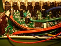
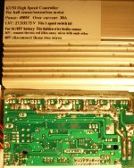
I have a 6Fet and a 9Fet KU93 controller here. I'll just test how many e-rpm they do
both are unmodified, note the better soldered traces of the newer KU93 and the increased current limit. Older KU93 have 25amps limit, newer are 30amps and have adjustable LVC, note the print on the label.
both are unmodified, note the better soldered traces of the newer KU93 and the increased current limit. Older KU93 have 25amps limit, newer are 30amps and have adjustable LVC, note the print on the label.
Attachments
crossbreak
1 MW
Tested the KU93 with N6354 in Star @ 46Volts. Frequency was 566Hz  something went wrong here, this would mean that the N6354 would have 53KV, thats half of what I expected
Edit: one has to devide E-rpm by p, not 2p, that means 7 for my star terminated N6354. The KV of 105.5 is just about right.
Edit: one has to devide E-rpm by p, not 2p, that means 7 for my star terminated N6354. The KV of 105.5 is just about right.
crossbreak
1 MW
when running that motor as a generator I can measure 15V @ 253Hz. It's a 14pole motor. So I calc 253Hz*60/7=2168.6rpm. That would mean a KV of 144.6 rpm/V. what went wrong here?
Guess nothing. Seem like leaderhobby just made some mistake when rating this motor. The 15turn N6354 is about 180KV, rather than 200KV as stated.
Guess nothing. Seem like leaderhobby just made some mistake when rating this motor. The 15turn N6354 is about 180KV, rather than 200KV as stated.
What are you using to measure the voltage?
The battery voltage feeding the controller will be closer to the peak-to-peak voltage. A good Fluke meter in AC mode will measure RMS, and one one phase at a time.
I'm not sure, but I think the RMS voltage is the one to use for the calculation. Need to research that one.
EDIT:
After some research, it seems to be quite complex for a 3 phase brushless motor.
What really counts from a practical standpoint is how fast it will go for a given pack voltage, so that seems to be the most useful way to measure, even if it is not 'technically correct'.
crossbreak
1 MW
thx for the help. I'll repeat these tests using the 80cc rotomax. Hope I have got a inductance meter and an oscilloscope by that time...
will be interesting to see if the X8M06-C can drive it properly.
will be interesting to see if the X8M06-C can drive it properly.
crossbreak
1 MW
ok the max frequency I got with the 80cc is around 700Hz. That are round about 42.000 electrical rpm. Looks like I have to rewind my 80cc to about 80KV. 11Turns in Star = 81KV would be close enough I guess. At 50Volts / 12s Lipo I should see round about 40.000 e-rpm.
An 80-85 170KV motor would have around 100KV in Star config. With 7 pole pairs this would be well below the 40krpm limit. A very cheap and simple drive...Same with the 80-100-180KV.
An 80-85 170KV motor would have around 100KV in Star config. With 7 pole pairs this would be well below the 40krpm limit. A very cheap and simple drive...Same with the 80-100-180KV.
crossbreak
1 MW
Ok I found out that th 50cc Rotomax has 28poles. That would be max 2860rpm for the X8M06-c controllers  I would have to rewind them to 57KV :lol: Guess i'll stick to the dual N6354 solution, it's cheapest, most simple and most lightweight and will still run almost silent. Any thoughts here?
went further with the CAD design and renamed the thread to "Coaxial-BB-Jackshaft Middrive with TGY Rotomax 80cc Build/Design". It's still the thing with counter rotating Jackshaft, a bit like the Panasonic drive (view http://endless-sphere.com/w/index.php/EBike_Motors_Middrive#Panasonic_Configuration)
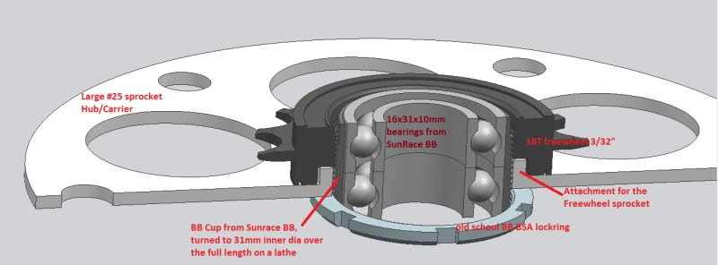
There is a detailed pic of the BB-coaxial-Jackshaft-Hub, that I can fabricate with home tools and off the shelf parts - just like I always do...
The bearings will be aligned axially by locktite, also the freewheel will be screwed on the BB-Cup with locktite, since there will be only 5 thread turns engaged to it.
Metal plus Metal Glue has proven to be a bomb proof combination. Just watch Doctorbass test videos!


How I will machine the assembly:
For machining the sprocket adapter, i will make a plate with 150mm outer dia and a 16mm bore, since the 95T 6mm sprocket that comes from maedler has a 16mm bore. This way I can match the connecting holes so that the sprocket is centered perfectly. I will then insert chain wheel screws to connect them.
In the next step I will cut the sheet, so I can bend the four freewheel attachments. After bending them in a 90° angle, I will cut/file the final hole that fits the BSA threads. I will file it to about 32mm and not further to the final 34mm yet.
How can I file this so that it gets centered perfectly? I use the 16mm BB-shaft and insert it to the BB-Cup with a bearing. this way I can always test if I already filed too far in every angle. The 95T sprocket from maedler still has the 16mm hole! The fact that this matches, is a stroke of luck
This is somewhat time consuming, but it proves to be the best way if one has no large lathe. Got some experience now from the Hub-to-middrive-motor-conversion and some other projects, I want to share for DIY people. Still, using this technique, I have spend less time than it would have taken to buy a large lathe I guess
Maybe such things can be done on a 3D printer in the future, just have to use it as a CNC mill... hope there will be multi-purpose machines (3D-printing, Laser cutting, plasma cutting, CNC milling and turning for plastic and alloy.... and so on with ONE small machine, it's possilble! And it should be programmed easy and quick! Maybe I should build that one in 2014 instead of eBike #7 :lol:
I would have to rewind them to 57KV :lol: Guess i'll stick to the dual N6354 solution, it's cheapest, most simple and most lightweight and will still run almost silent. Any thoughts here? went further with the CAD design and renamed the thread to "Coaxial-BB-Jackshaft Middrive with TGY Rotomax 80cc Build/Design". It's still the thing with counter rotating Jackshaft, a bit like the Panasonic drive (view http://endless-sphere.com/w/index.php/EBike_Motors_Middrive#Panasonic_Configuration)
There is a detailed pic of the BB-coaxial-Jackshaft-Hub, that I can fabricate with home tools and off the shelf parts - just like I always do...
The bearings will be aligned axially by locktite, also the freewheel will be screwed on the BB-Cup with locktite, since there will be only 5 thread turns engaged to it.
Metal plus Metal Glue has proven to be a bomb proof combination. Just watch Doctorbass test videos!
How I will machine the assembly:
For machining the sprocket adapter, i will make a plate with 150mm outer dia and a 16mm bore, since the 95T 6mm sprocket that comes from maedler has a 16mm bore. This way I can match the connecting holes so that the sprocket is centered perfectly. I will then insert chain wheel screws to connect them.
In the next step I will cut the sheet, so I can bend the four freewheel attachments. After bending them in a 90° angle, I will cut/file the final hole that fits the BSA threads. I will file it to about 32mm and not further to the final 34mm yet.
How can I file this so that it gets centered perfectly? I use the 16mm BB-shaft and insert it to the BB-Cup with a bearing. this way I can always test if I already filed too far in every angle. The 95T sprocket from maedler still has the 16mm hole! The fact that this matches, is a stroke of luck
This is somewhat time consuming, but it proves to be the best way if one has no large lathe. Got some experience now from the Hub-to-middrive-motor-conversion and some other projects, I want to share for DIY people. Still, using this technique, I have spend less time than it would have taken to buy a large lathe I guess
Maybe such things can be done on a 3D printer in the future, just have to use it as a CNC mill... hope there will be multi-purpose machines (3D-printing, Laser cutting, plasma cutting, CNC milling and turning for plastic and alloy.... and so on with ONE small machine, it's possilble! And it should be programmed easy and quick! Maybe I should build that one in 2014 instead of eBike #7 :lol:
wannabeaflyer
10 µW
- Joined
- Mar 16, 2012
- Messages
- 6
Hi guys i'll appologize now if this info can be found elswhere on this fantasic forum, im looking for a cad model of the 150cc rotomax unit ,, i have come across it somewhere here before but for the life of me cant seem to find it again can anyone direct me to the location or provide a link please . thanks to the Photos on this thread i can make a basic model but need some more Dimensions for my project. cheers guys
crossbreak
1 MW
I know nothing about that. Would you like to make one if I give you the measurements?
mr.electric
10 kW
So what is the coaxial jack shaft like in operation. Can it really be made with hand tools. I love making parts without machine tools.
From what I can see in the drawling the coaxial shaft eliminates the need for a jack shaft to be mounted far forward like the GNG but necessitates a complex chain path with a few idlers.
Im awaiting pictures of the proof of concept build by Crossbreak.
From what I can see in the drawling the coaxial shaft eliminates the need for a jack shaft to be mounted far forward like the GNG but necessitates a complex chain path with a few idlers.
Im awaiting pictures of the proof of concept build by Crossbreak.
crossbreak
1 MW
From what I can see in the drawling the coaxial shaft eliminates the need for a jack shaft to be mounted far forward like the GNG but necessitates a complex chain path with a few idlers.
There is one additional idler in the final drive chain. Yeah, this is definitely a con. The Panasonic drive also uses this additional idler.
The pro is that one can use a larger reduction ratio with less impact/space usage.
Anothor Pro is, that a jackshaft is used for the pedal drive. This way the pedal speed can be speeded up to an equivalent of an 88T chain wheel. So it's possible to pedal at high speeds and use the larger and more durable sprockets on the rear wheel.
Another con is that again a special longer BB is needed that allows mounting motor sheets and a lockring to fasten them, just like the GNG drive.
this sadly has to wait a few months.Im awaiting pictures of the proof of concept build by Crossbreak.
bzhwindtalker
100 kW
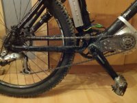
I tried a configuration similar to what you show in this picture with my GNG and before that with a 64-73 rc motor, exepted that the chain did not go round the pedals. in the two cases the whole unit twisted like crazy under load and did not feel solid at all. I'm not saying It cant be done, just that you will need to make your jackshaft really strong and rigid.
crossbreak
1 MW
I dont get your config. There are no chains go round any pedals with mine, that's some special... do you have a pic?
crossbreak
1 MW
this one feels really stiff, it has only 1.5mm mount sheets and feels quite solid at 1500W input and 2200N chain force.. I still dont get it :?
My new drive is calced so it wont exceed 2500N chain pull to not overstress the final drive chain also...keeps the forces on the mount down
My new drive is calced so it wont exceed 2500N chain pull to not overstress the final drive chain also...keeps the forces on the mount down
Attachments
crossbreak
1 MW
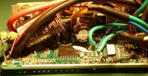
The 15 and the 24fet sensorless controllers have arrived. Sadly had time to test the 15fet one only. Looks almost exactly like the KUxx series, same chip, just the fets are different. I ordered irfb3077 since I will not exceed 60volts due legal issues.
The behavior is different than the KUxx behavior: when it reaches almost 40000erpm, the motor does not stop immediately, it just does not spin up any further. Also, the sensorless start up is faster on delta wound motors. Did not try any star wound one yet.
The behavior is different than the KUxx behavior: when it reaches almost 40000erpm, the motor does not stop immediately, it just does not spin up any further. Also, the sensorless start up is faster on delta wound motors. Did not try any star wound one yet.
crossbreak
1 MW
Hope so too ATM I've got too much to do with my HS3540 bike, my dual freewheel Jackshaft bike (shall get a converted Bafang BPM soon) and my friction drive bike, i'm also programming some kind of cycle analyst and i'm planing my eBike test bench...so this sadly has to wait some mounths
The 80cc Rotomax is still sitting on my bench, looking at me every day, waiting to set free its power...the 24Fet sensorless sits right behind it
I recently had some dead cells in one of my packs thats why I care for a perfect warikng BMS ATM. I'm still working on the SmartBMS with the O2 chip, hope I can at least come up with some progress on that building site:
http://endless-sphere.com/forums/viewtopic.php?f=2&t=47124 and http://endless-sphere.com/forums/viewtopic.php?f=14&t=48461
ATM I've got too much to do with my HS3540 bike, my dual freewheel Jackshaft bike (shall get a converted Bafang BPM soon) and my friction drive bike, i'm also programming some kind of cycle analyst and i'm planing my eBike test bench...so this sadly has to wait some mounths The 80cc Rotomax is still sitting on my bench, looking at me every day, waiting to set free its power...the 24Fet sensorless sits right behind it
I recently had some dead cells in one of my packs
thats why I care for a perfect warikng BMS ATM. I'm still working on the SmartBMS with the O2 chip, hope I can at least come up with some progress on that building site:http://endless-sphere.com/forums/viewtopic.php?f=2&t=47124 and http://endless-sphere.com/forums/viewtopic.php?f=14&t=48461
Danny Mayes
1 kW
crossbreak said:I know nothing about that. Would you like to make one if I give you the measurements?
I'll do it crossbreak.
Are you still happy to share the measurements.
I'll post it when I am done.
It will be in inventor format.
I would like the model to be as accurate as possible so that means a lot of measurements. Are you up for that?
Danny
Edit: Duh, just read the tread, pictures on last page. I initially arrived on this page from searching for a rotomax model.
I will use what you have posted to create the model for now and go from there. D
Edit 2: I will not be doing this now. Commitments have changed so this wont be happening. Sorry for the broken promise. Hope someone who has the time can create a good model for it. D
Tommy L
100 kW
Subscribed! Nice work here!
Tommy L sends.....

Tommy L sends.....