Connectors and Crimpers Question

Zoot Katz

100 kW
Joined
Jun 21, 2008
Messages
1,543
Location
Vancouver, BC Canada
Just as I was finishing the last solder joint it dawned on me that I'd not be able to remove the controller or VeeRack on my Xtracycle unless I cut or de soldered the wires powering my lights. . . the ones I'd just installed!
No problem, I'll buy some connectors and pop those on in an hour or so. Delusional is the word that best describes that notion.
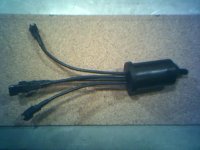
The connectors in question are the assorted ones sold by ebikes.ca and pictured below.

Got 'em home, snipped all the wires and proceeded to get more flummoxed and frustrated as the hour turned into three without achieving credible results.
Those things are tiny. Too tiny for the crummy crimper I own. The wire looks to be smaller than AWG 24. The only way I could get things to sorta work is by tinning the wires and heating the pin so the wire would sorta stick and permit mangling the prongs on the pin to hold it long enough to make a good solder joint. My lack of technique produced results that are not acceptable.

So the questions are, what are those connectors called? And what sort of crimper do they require? They're the same type connector as those used on the Cycle Analyst.

Any tips, even the most basic stuff everybody should know, will be most welcome.

ConBag.jpg
 
funny

i used to work in this business before getting out.

if these are JST parts (my old company), the crimp tool is WC-121. you can get them from digikey. it may be a few hundred dollars or so-- but it's a nice tool (i used to sell them). if that's too rich for your blood, you might be able to find a generic tool but it'll be more difficult to use.

you can find the info at http://www.jst.com
 
look for pc molex thay are very cheep and there's a tool that gos into the plastic bit and it closes the feet in the male pegs so you can remove them.i use a screwdriver(small and bend them in a little bit then bend them back out be for putting back in.click sorted/

http://cgi.ebay.co.uk/Molex-Pin-Connector-Removal-Tool-Male-Female_W0QQitemZ190273508476QQihZ009QQcategoryZ75520QQtcZphotoQQcmdZViewItem
 
jondoh said:
funny

i used to work in this business before getting out.

if these are JST parts (my old company), the crimp tool is WC-121. you can get them from digikey. it may be a few hundred dollars or so-- but it's a nice tool (i used to sell them). if that's too rich for your blood, you might be able to find a generic tool but it'll be more difficult to use.

you can find the info at http://www.jst.com

WC-121 is $440 now. Gulp! That's too much information all at once. I'm thinking it might be possible to modify some cheap minature pliers.

Thanks for the link to a quick descent into acronym hell.
The alphabet soup of "wire to wire" connectors will have me swimming for awhile trying to figure out what these things are called.
Any hints?

Thanks again.
 
Sir, that's exactly what I needed to know to convince me that maybe I might know somebody who knows somebody who may be able to install those connectors on the raw ends of the lights' cables and make up a few pigtails I can solder into the switch and controller.
You can see that I'm hoping to get away with the cost for a box of local micro-brew instead of shelling out to your former employer.

This afternoon I returned everything to how it was before, except with shorter wires, until such time as it needs repair, upgrading or never.
Whichever comes first.

I'd like to improve the switching so I can turn off the lights. Presently they can be switched between solid and blinking modes only. I do encourage daytime running lights for visibility but sometimes I'd like to leave the bike on and the lights off. . . like full moon rides on a clear night. Off road your eyes adjust to the light levels.
Eventually perhaps incorporate turn-signals too into a submersible handlebar mounted switch about the size of a bicycle ping bell. A cell-phone navigation switch and circuit would also permit switching to front solid/rear blinking and vice versa.
Problem is I ain't got the chops.

Thank you for your generosity.
 
I've never been a fan of crimped connections. Even after I crimp them, I usually solder 'em anyways.

To that end, I've never had any difficulty carefully closing the crimp with a pair of needlenose pliers and then soldering the joint. In fact, I'm happier with this than I would be with "proper" crimps. Albeit, if you were doing it all day long, a proper crimp tool is way faster - but for the low volume I do, I like to think soldering is better.

If you've taken apart some of the connectors you see on some of the kits out there, the contacts aren't crimped AT ALL. The wire is just laid loose in the valley of the pin body and soldered, leaving the "ears" that should have been crimped just flying. Of course, some connectors (Andersons for example) won't go together without crimping the pin, but even this is easily accomplished.

On the other hand, if your soldering iron isn't designed for this kind of work, you'll have trouble (those old Weller guns come to mind - completely useless in my world).

Having said all that, I've got a box of connectors coming from Justin (Zev shipped them yesterday) - which includes three of those grab bags of the very connectors you are working with. If I wind up having to eat crow because there is something different about the pins (haven't seen 'em yet), you'll be the first to know :)
 
Yes, long nosed pliers as philf says usually works.

I try to get just a poor crimping connection first, just enough to follow it up with a good soldering job without anything moving.

Strap-on illuminated magnifying glasses are the go for all of these jobs (for me, anyway). They get placed around the small fire extinguisher after each use somewhere on the workbench, so I always know where either of them are....

To solve your immediate problem you could also just use a switch with srew-on terminals to enable disassembly without cutting or desoldering.
 
Thanks to all the helpful people sharing their experience, I succeeded in making one of the three 3-pin pigtails I'm going to need. Two others are soldered and are awaiting having their ears bent. They must be formed carefully to fully fit into the housings.
Philf, your tip to bend one ear at a time was the key to getting these tiny bastards sorted. Now if I can just develop some consistency things should proceed swimmingly.
Mr. Mik, I too am in need of some sort of magnification for this stuff. It's the price we pay for achieving maturity. A pair of those binocular magnifiers would certainly enhance my enjoyment of these types of jobs. I tried your method of getting a crimp first and then soldering but had too hard a time holding the wire and pin in position. Philf's method of first filling the valley with molten lead worked better for me.

Still they're dogs and not the simple solution I was hoping for. I will persevere until the results are satisfactory. Last night I was ready to fob the job off to somebody else. Today I'm resigned to stripping the lights and controller so I can fiddle around with them on the bench instead of trying to accomplish the work while they're attached to the bike.
 
My past frustrations, and how I've overcome them, never factor in to my stream-of-consciousness when I talk about things I'm doing *now*. I completely relate to Zoot's plight - being reminded that you have only two hands in the same instant you discover the need of a third.

As hokey as it is, I've completed countless "three-handed" manoevres using nothing more than a crappy clamp-thingy I got from Radio Shack eons ago (and which are still available from numerous sources). The original unit, as sold, came with a poor quality plastic magnifying glass and a bunch of roach clips to hold your work to a pseudo-articulated boom that's attached to a reasonably heavy base (for its size).

extrahands.jpg


I replaced the roach clips with cheap clothespin-sytle clamps that Home Depot were selling as impulse items at the cash (think I bought a handful of them for something like 49 cents each). The original clips were fine, but these ones had more bite for something I needed the bite for - never put the original clips back.

Anyways, I've done lots with this Mickey Mouse rig, and still use it more often than some of other tools I have which would try to replace it.

The picture shows both my left and right hands free (nose took picture), while a 45A Anderson contact rests atop a piece of 10gauge wire awaiting solder. As mentioned in prior posts, the contact has merely been clipped to the wire with small needlenose pliers at this point.

I've done this same thing by taping the wire to the lip of my desk/work surface when I couldn't find the other tool(s) :)
 
I made the little 3rd hand jig thing here before I'd even posted this subject.
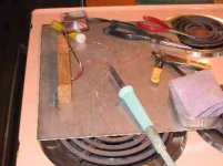
The impromptu soldering bench has good light and ventilation.
stovetop_solder.jpg

I think it's funny that a question about crimp on connectors was accurately and completely answered and the subject changed to work-around techniques.
The female pins are going to be more difficult because I won't be able to reach around and pull them through to get the barbs to catch. They may require cutting off the ears and relying on solder and hot melt heat shrink for strength.
I'm in the process of salvaging some better switches than the one I have. I didn't want to tear down the bike just to use the same crappy switch again.
 
Zoot Katz said:
The female pins are going to be more difficult because I won't be able to reach around and pull them through to get the barbs to catch. They may require cutting off the ears and relying on solder and hot melt heat shrink for strength.

OK. I can't envision what you mean, here. Inserting the female pins into a connector body should be exactly the same process you use for a male pin!
 
philf said:
Zoot Katz said:
The female pins are going to be more difficult because I won't be able to reach around and pull them through to get the barbs to catch. They may require cutting off the ears and relying on solder and hot melt heat shrink for strength.

OK. I can't envision what you mean, here. Inserting the female pins into a connector body should be exactly the same process you use for a male pin!
It probably is just as easy with perfectly formed crimps. My crimps weren't perfect and the male pins had to be persuaded into their slots by pulling on the pin from the open end of the connector. That's not an option with the female pins so they're going to require more care in forming the crimps.

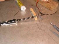
Heres a female pin in improvised clamps. The cross lock tweezers are secured to the edge of the stainless steel work surface with a Bulldog type paper clip. The wood spring clothes peg keeps the toothed tweezers tips from deflecting under soldering pressure. The roach clip is crimped poorly onto stranded copper wire. It rotates just enough to approximate precise placement.
Now I need binoculars and maybe results will improve. I've got a few to burn while practicing techinque until I start incrementally shortening the cables.
stovetop_solder_junk-rig.jpg

I used to enjoy tying the tiniest trout flies, scratch building miniatures, scale ship models and rubber powered airplanes weighing about two grams. I even built a Heathkit amplifier, speakers and cassette deck once upon a time.
 
Zoots, you're a howl.

You remind me of a fellow who I used to spend a lot of time with, and picked to be my "Best Man" when I got married so many eons ago (unfortunately, the marriage only stuck for 8 1/2 years). I really wish there were more like you.

"Best Man"... WTF does that MEAN, anyways? :)

I really can't wait (or maybe I can?) to get the connectors from RBC so I can share your pain...

I get the sense that I'm not going to have any fun with these connectors at all. My reason for ordering a few bags of them was to make it possible for me to rework the stuff I have into a consistent interface scheme (thus making it easier to "mix and match" components). Sounds like I'll be using my best wallpapering language to get there...
 
philf said:
Zoots, you're a howl.

You remind me of a fellow who I used to spend a lot of time with, and picked to be my "Best Man" when I got married so many eons ago (unfortunately, the marriage only stuck for 8 1/2 years). I really wish there were more like you.

"Best Man"... WTF does that MEAN, anyways? :)

I really can't wait (or maybe I can?) to get the connectors from RBC so I can share your pain...

I get the sense that I'm not going to have any fun with these connectors at all. My reason for ordering a few bags of them was to make it possible for me to rework the stuff I have into a consistent interface scheme (thus making it easier to "mix and match" components). Sounds like I'll be using my best wallpapering language to get there...

The particular reason I wanted to know what the connectors were properly called is because none of the things I'd called them seemed to be the magic word. The pain isn't as harsh as smacking yourself good with a hammer but you have to keep doing over and over again.

The latest iterations of "the jig" employs one of my favourite axioms, "simplificate and add lightness".
Visualise two alligator clips held vertically in the jaws of two wooden spring clothes pegs. They're much easier to align than the wire thingy and they hold the female pin more securely than the tweezers. Changing to a cork work surface and the addition of some weights kept the clothes pegs from sliding.

Removing all the ears completely has so far worked better than trying to bend the stubs of the cropped ears into compliance. Test the solder joint before inserting the pin into the housing. A broken joint leaves the pins stuck inside the housing where they're easy to mangle irretrievably if one is forced to attempt extraction.
 
What I learned of crimpers was practically zip. Good ones are expensive but probably worth the bux if you're a pro. The same is true for any trades tools. Even without trying the WC-121 crimper on these dinky SM series connectors (thanks jonduh) I can say they'd not have been worth $400 to make eleven pairs of connections. The work around turned out to be more fun for masochists like me. Thirteen female pins, seven male pins, about 25cm of cable and one half of a plastic connector body were sacrificed to research. Various failures lead to eventual success. I'm appreciative of the helpful contributors who offered information, tips and encouragement.
Cheap binoculars finally made it all possible again as I already had a variety of experience working on small scale objects. Soldering (and de-soldering) skills came back quick enough.
The camera went haywire again last night after I'd jury-rigged a mount and read up on how to do macro shots of the finally evolved clamping and soldering methods that worked.
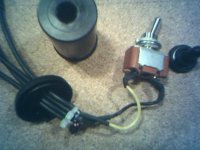
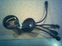
Phone pics of the partial results:
View attachment 3
switch_ready.jpg
switch_set.jpg
switch_done.jpg
 
Back
Top