Let's try again.
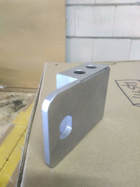
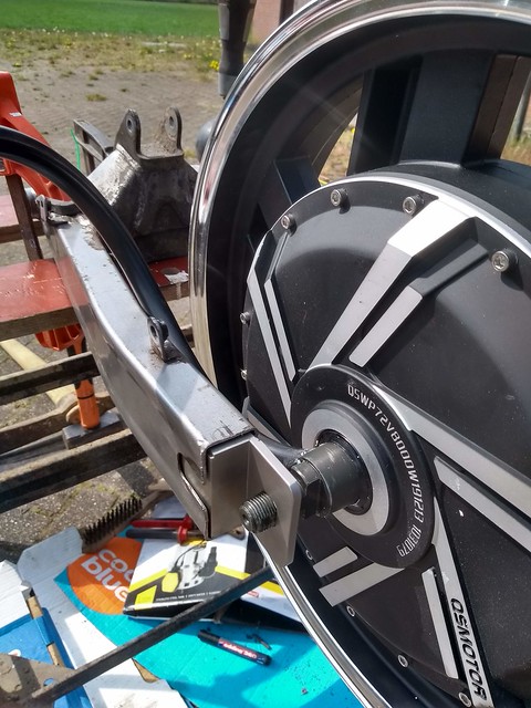
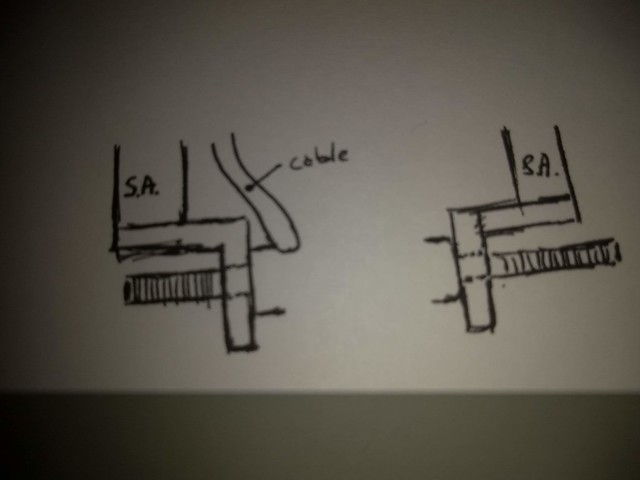
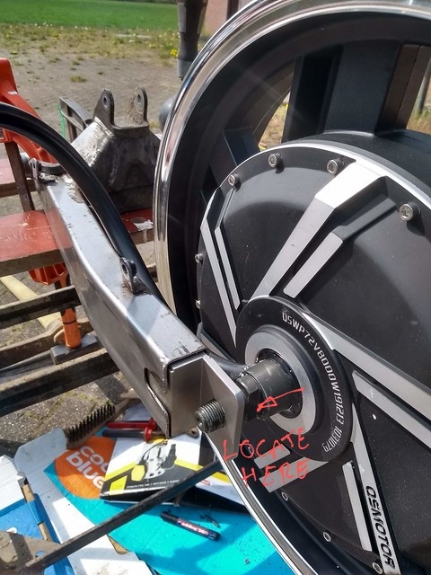
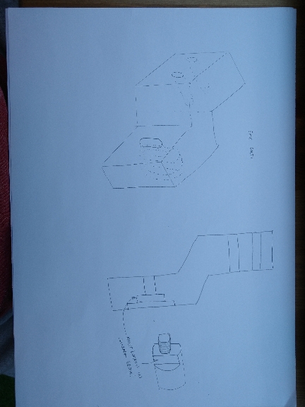
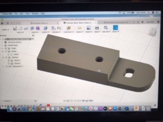
The large flat of the main shaft I pointed to above needs to locate in the block.
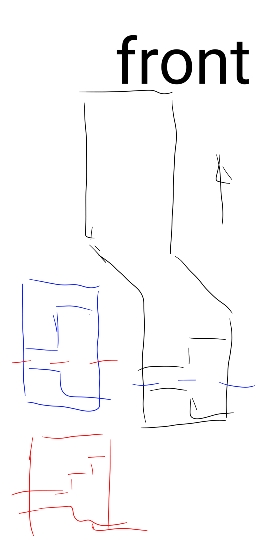
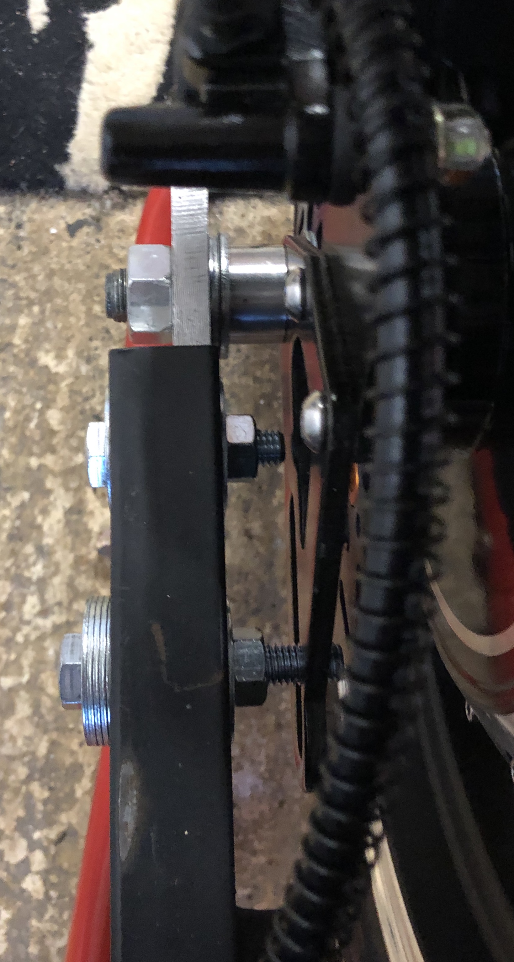
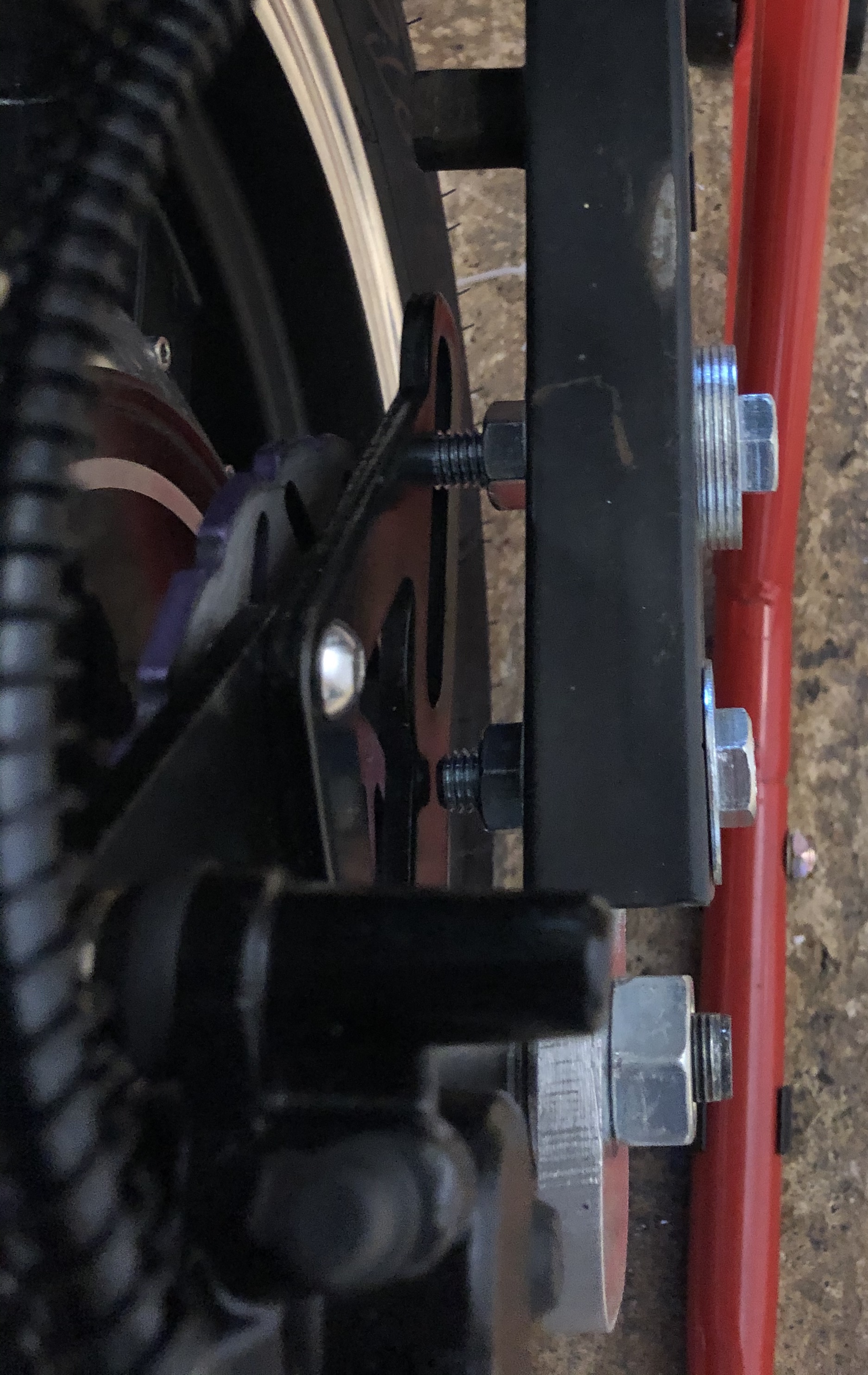
Also, I agree with swiftyds's design in clamping the swingarm horizontally. This will give better surface area and flex for clamping force. I'd use a high tensile 10mm bolt. And to support this, since the block is longer again in my sketch for the angled section, I'd trim the swingarm a little more to remove the last remnants of the axle slot and make room for bolting.
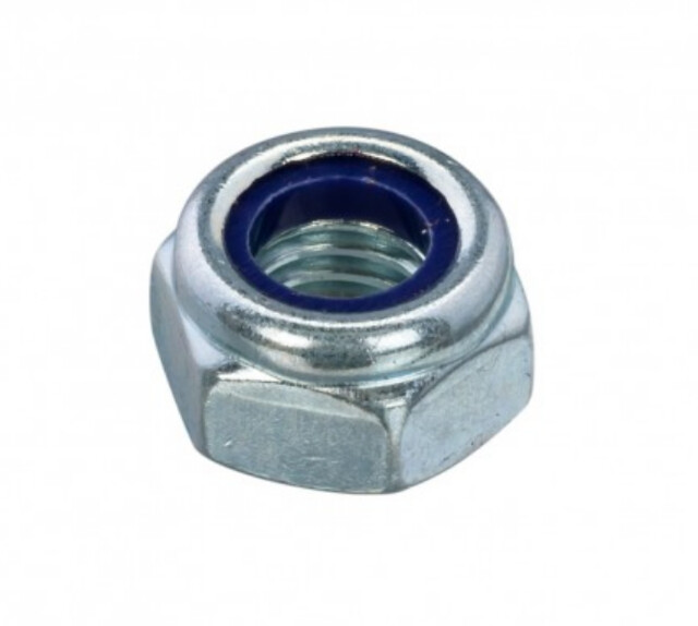
PS: you can use this bolting for securing the brake torque arm also, use the forward most bolt and bolt through both swingarm and torque arm together. I'd probably boot the swingarm then sandwich the torque arm with a second nut ie bolt through swingarm then but then torque arm then second nut. Nuts act as locking mechanism to each other as well then.
I apologise if I'm upsetting your build plan but your original design worries me and I'm confident unless you have a separate torque arm fixing where I say, that axle is just going to strip and spin, possibly even snap off the way you show it. Perhaps I'm missing something.
Cheers
Tyler

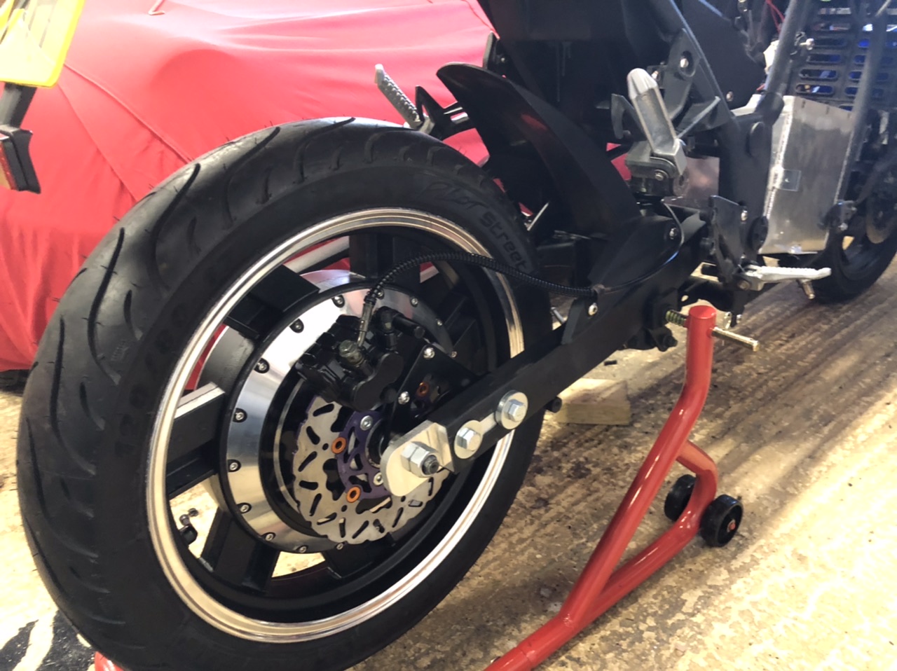
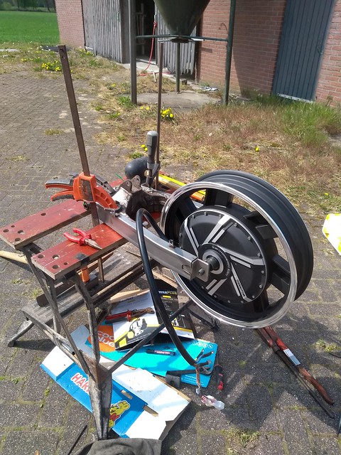
 Tomorrow I'll reintall the swingarm into the motorcycle and post an update again. Can't wait to see how that looks!