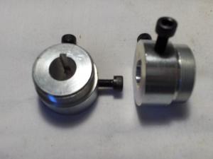
The flats are not going to do well at high torques. I've seen some freewheel adapters that have a keyway:
http://www.staton-inc.com/store/pro..._Sprockets_1_10_wide_2_set_screws-874-27.html
Making a slot in the axle shaft and using a key of some sort would probably be much stronger.
A ghetto way to make the key is to drill into the axle and insert a piece of drill rod that sticks out enough to engage the keyway on the adapter. Maybe two rods. Otherwise using a dremel tool it may be possible to grind a keyway into the shaft.
The bolts sticking out in the picture could be replaced with set screws to keep it flush.