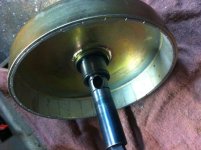
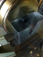
Converting a hubmotor to a middrivemotor

I remember on several MX bikes I had ridden years ago, the ones with larger flywheels / crank mass, having noticeably more gyro effect. I would guess that the greater the rotating mass and the further off the ground the bigger the effect. Would be interesting to compare two e-builds with similar motors at very different motor heights.
 
Green Machine said:
fechter said:
Interesting about the gyroscopic action. I think it would be about the same if the motor was hub mounted.
But now i am noticing that it does happen to lesser extent in a hub in the wheel bike as well although not as pronounced. Where you really feel it is a bike with the motor mounted in the front wheel because it does weird things to your steering.
....
I guess it is just something you need to understand and get use too .... Maybe gyroscopic effect can be a good thing...less likely to fall over? IF you just compensate by leaning harder into the corners and not be alarmed that the bike is trying to right itself maybe it will be good.
I have two BMCs in 26" wheels with Fat Franks so they sit fairly high up. There is definitely an effect, but as you mention, different isn't necessarily bad. It's actually pretty nice at speed in blustery wind. I find that countersteering is very effective - once you get in the habit, the bike just falls into the turns pretty nicely.
 
I think (in theory) it shouldn't matter how high off the ground it is since it's rigidly attached to the frame and the force is a torque applied to the frame.
Changing the center of gravity has it's own set of effects.

With a freewheeling motor, it should be easy enough to test a corner with and without the motor running to see what the difference is.
 
Hi,

fechter said:
I think (in theory) it shouldn't matter how high off the ground it is since it's rigidly attached to the frame and the force is a torque applied to the frame.
I think (in theory):
1. If it's higher it will have more force (a longer lever).
2. Moving the motor down far enough that the shaft is at the same height as the rear sprocket/front crank will probably reduce the effect substantially. That was where Marcus had his motors and with years of prototypes he never even noticed this issue. IMO the other two possibilities are that with the mac this problem is bad (unusually heavy rotating mass) or the issue is the mac with crossbreak's mod (heavier rotating mass?).
 
Here is the Picycle that Mitch is referring too with its ultra low hub motor mounting. As a side note this bike and Marcus is what inspired Dan Hanebrink to make his hub mounted mid drive sand bike. Dan Hanebrink actually helped design and build the mid drive Pi cycle. I talked to Dan Hanebrink yesterday about this gyroscopic effect and he says he considered this issue when designing his sand ebike and by using 20 inch tires and keeping the center of gravity low he is able to minimize gyroscopic effect on his bike but thinks it would be a bigger factor on 26 inch tired bikes. In my case my tires end up being 29 inches so the bike is extra high.
 

Attachments

  • picycle.jpg
    picycle.jpg
    46.9 KB · Views: 2,571
Green Machine said:
Hi Guys,

Can anyone comment who has attempted this build with a mac motor, Is a shim or washer to space the axle needed on the Mac motor conversion?

I know it was needed on mr electric's bmc conversion but as Bob said the mac is a different animal.

Green Machine,

"I think" this post http://endless-sphere.com/forums/viewtopic.php?f=28&t=46568&p=684647#p684647 on a different thread will answer your question and tell you what effects the clearances in the MAC motor conversion. In my conversion the only shim I used was a very thin shim between the clutch hub and the snap ring on this side of the hub

P1190492.JPG

BUT, if you are using an older clutch, this may change. Since then I have made a shaft from "scratch" for the conversion that will only have a single groove for double snap rings on the side of the clutch shown and shims for cover clearance on the opposite side. The only keyway inside the motor necessary for conversion is the one for the clutch.

If you need more information, I will be glad to respond.

bØb
 
I got a Mac motor open today. I think it will work as well or better than bmc as a mid motor. The differences in the construction make the conversion process easier on the Mac. As far as I see the spacer tube is not needed and the there is no need to make new threaded holes in the stator.
I am working with a few other ES members to convert the motor. I received the motor with an adjustable bracket and new side cover/ heat bridge.
I will be wiring the motor and installing it in the frame. ImageUploadedByTapatalk1358915902.597856.jpg
I found some drag when spinning the motor and found these scratches inside.
ImageUploadedByTapatalk1358915968.209369.jpg
ImageUploadedByTapatalk1358916455.329685.jpgIt seems like the only reason the motor drags like this is because the circlips are not installed. ImageUploadedByTapatalk1358916095.451924.jpg
I think it needs the large innermost circlip and the outermost shaft circlip installed to prevent the grinding of the planet shaft ends and the rotor as shown that was happening.
ImageUploadedByTapatalk1358916259.109339.jpgI used these hardware store 2x4 brackets I had lying around to hold the rotor when pulling the stator out. I would not clamp the rotor shell or sun gear in a vice for fear of breaking a magnet or damaging the gear.
 
I believe the BMC has thinner laminations, and due to that I suspect they "may" be using a slightly better steel in the lams. The BMC should run a little cooler than the MAC, and the efficiency should be slightly better. There is a noticable price difference, so I believe the MAC will prove to be much more popular for conversion because of the lower price and the available selection of 5 Kv's (instead of two kV's for the BMC).

edit: I now believe the Bafang BPM is the best candidate for conversion, or even for use as a non-hub without converting it, with the MAC in second place. The BMC is not bad, but it provides no extra benefit and it is $575 for the bare motor alone.
 
I believe so also so that is what I have already done with my MAC conversion. Nice job on the custom side plate I may have to do the same just for better heat transfer through a thicker cover but time will tell..
 
The low Kv of the 12T MAC may turn out to be too low, but it will be a useful experiment for a 72V system being used at fairly low speeds when off-road. Once actual results are obtained, voltages, Kv's, and gearing can be better guessed at for other applications. for 48V on 30-MPH street E-bike, a 6T, 8T, or 10T may prove to be better for the reasons you mention.

If you wanted to go the high-RPM motor route with an external gear-reduction, the Bafang might provide a good option because is has fewer poles, and would be easier on a sensorless controller due to the lower electrical frequency.

edit: The Bafang is the only candidate (compared to the BMC / MAC) that is useful for high RPMs, due to excessive eddy-current heat if the BMC/MAC is used above 1,300-RPMs, with 1,000-RPMs being the best limit for optimum cool running. The Bafang "should be" able too be run up to 2,000-RPMs without any eddy-current waste-heat.
 
spinningmagnets said:
The low Kv of the 12T MAC may turn out to be too low, but it will be a useful experiment for a 72V system being used at fairly low speeds when off-road. Once actual results are obtained, votages, Kv's, and gearing can be better guessed at for other applications. for 48V on 30-MPH street E-bike, a 6T, 8T, or 10T may prove to be better for the reasons you mention.

If you wanted to go the high-RPM motor route with an external gear-reduction, the Bafang might provide a good option because is has fewer poles, and would be easier on a sensorless controller due to the lower electrical frequency.

It kind of depends on what you are looking for. For all out performance the 6T or 8T would be best. BUT if you are looking for best efficiency or range, I believe the 12T MAC would be better. I think gearing for the highest speed desired for the street is the best plan. If you insist on gearing for 10 mph top speed, the torque is just going to be off the scale. Much more than you could apply to the ground. With 48v and a 12T MAC, if you could stall it, you're going to tear up something in the gear train.

bØb
 
rodgah said:
Actually speaking of Kv......

Assuming a traditional BB mount method, would it not be best to get the highest Kv, and gear down to the cranks with #219 or similar? more rpm means more power right? And the less torque the planetaries will see?

Rodger

Right. But there is an rpm limit where the MAC starts to get lossy because of its cheap 0.5mm laminations. 400rpm is the max i would calc with. Eddy current loss is independent of the wind. If you use a 12T@72V you will see the same result as with a 6T@36V. BMCs have 0.33mm lams, you can turn them a bit faster without wasting energy.

Personally i would stick to the 6T and use 12s lipo, set 30amps battery and 50amps phase current limit, to make the gears last.
 
Ok cool,

A bpm and a ku123 is definitely a cheap option though the Mac seems to be the easier. I was thinking more around the 40-50A at 12s, but mine would be used primarily offroad at speeds not much more than 25mph. I guess it's all speculation at the moment as to what will work.
 
Back again on topic about left side crank drives: I may have a solution that lasts.

I looked into details of the screw joint of the pedals. They are likely to loosen when used, since there is this counter rotating loosening effect discussed on sheldon brown webpage.

But what people forgot: A screw joint that has no pieces that elongate during fastening, will loose preload quickly (described in VDI2230 for example). Pedal screws have a very short piece that can elongate. That's why expansion screws are used with connecting rods in engines for example (not a good one here, different strain on the screw).

we may solve the preload issue by just adding a well fitting washer between pedal and crank, this way the piece that can elongate can easily be doubled. Additionally the washer is squeezed. Now add locktite and we are done (I hope). I'll test this on my bafang build. Hope I can drive a few hundred miles on it during the next months, we'll see if it will last.
 
Something like a real heavy duty spring washer (Bellville or wave) might do like you say. Cross-drilling the threads and pounding a pin in there would slow it down too.
 
unless you don't use LH threads or LH inserts in the left side, even the stronger glue could fail on that....these forces are like roots forces....a sum of strong micro rotations that could move a mountain.....
You are right about the elongation question.....the best way should be to use a conical lug coupling, though.
For a LH crankset that would have similar performance compared to the same RH one, the BB has to be considered too, cup's thread orientation (again) and spindle's bearings positions are, in fact, projected for a right chain load on an RH sprocket.
EDIT: That could be solved in my frame :D
panurge said:
faster than expected :wink:
file.php

You should also see the adjustable BB and the threads in the BB spacer for the derailleur tube where I actually clamp the Recumpence drive.
Also I have the ability to change the BB shell....
Some manufacturer, mostly for the tandem and BMX markets, offers Lh cranks and BB for these applications....
Copper and spring washers, glue, and even small welds are all good to add X Km of tightness life....but it's only a question of time....An LH thread or a conical coupling could lasts lifetime.
 
Thx for your ideas.

the BB has to be considered too, cup's thread orientation (again) and spindle's bearings positions are, in fact, projected for a right chain load on an RH sprocket.
Good point, but that wont be a problem on mine. Unlike regular square taper BBs, octalink BB are 70mm wide and almost symmetric.

Searched the net for LH drive cranks but found only BMX ones, they dont fit my octalink BB.

Thread inserts would cause costs that exceed the cost of the crank arms, thx anyway, StudEbiker. This would be an option for the higher priced builds.

Fechter idea of drilling the a small hole into the threads sounds like worth a try. I wont get the pedals off no more, but that doesn't bother me much since cranks are cheap. Thx fechter!
 

Attachments

  • LH_drive_crank_thread_pin.png
    LH_drive_crank_thread_pin.png
    2.6 KB · Views: 2,433
What if you drilled and tapped the inside ends of the pedal shafts? Then lock-tight some flanged bolts flush against the back side of the crank arm? Just a thought.
 
Why not just put some 271 Loctite on them and just try it.
You might be looking for a solution that doesn't have a problem :roll:

bØb
 
bØb said:
Why not just put some 271 Loctite on them and just try it.
You might be looking for a solution that doesn't have a problem :roll:


Well, that's just like my opinion. I'll stamp a mark on after that and just have a look if it moves. I'll use locktite 241, it's all i've got here right now.
 
fechter said:
Cross-drilling the threads and pounding a pin in there would slow it down too.
crossbreak said:
Fechter idea of drilling the a small hole into the threads sounds like worth a try. I wont get the pedals off no more...
I think he meant to drill it side to side through the diameter so the pin can be driven through and out the other side for removal.

And there's always Doc's famous DP-420 - if it's good enough to hold on his torque plates, this would be a walk in the park...
 
Back
Top