Custom Bosch / Yamaha battery

(the cells will still get balanced when charging, and still be protected from low voltage damage from the controllers operating range)
 
Pwnlord187 said:
If you bypass the discharge on your Yamaha battery pcb (cut the thick red/black wires going to the board from the discharge port, and solder them to the main leads of the pack, which are oval shaped solder pads on each end, the one closest to the port is positive) if you do this you won't be restricted by yamahas discharge limits, which are set to be overly conservative compared to how the cells can actually perform
At what voltage does the yamaha and or bosch packs usually cut out at?
 
gamerpaddy said:
sorry for late post.
but i reverse engineered the yamaha battery a year ago.


in case you want to build your own.
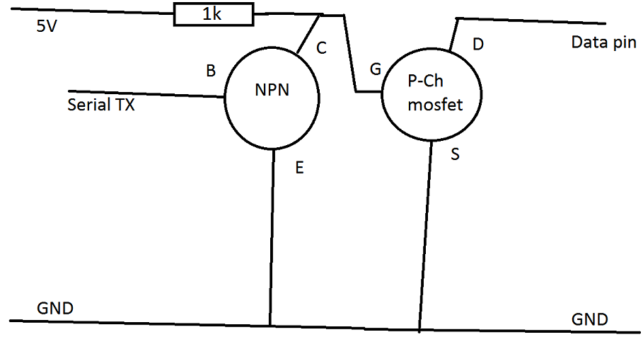
Just get a Arduino compatible board and a few discrete components.

Add a 5V source, i usually use a LM2596HV dc dc converter for this. A USB powerbank or even running it from two or three Cells on the pack (VIN pin of the arduino) will work.

Optional: To monitor the voltage add a voltage divider set to a ratio of 7.401 (42v in 5v out) and connect it to the A0 pin of the Arduino.

Edit this code https://pastebin.com/34SdehGt
>Edit line 35 to match your voltage divider. calculate or test to find out ADC values.
>Change line 44 and 45 (the number 20) to a value you want. 20 means it averages the current voltage 20 times to smooth it out. 20 is 5 seconds.
>Remove line 50 if you dont want your indicator to stay at 10% even if its lower. this prevent turning the motor off when voltage drops driving up a hill.

After that, Flash it in Arduino IDE

Wire it up like this.
kmj82Ho.png


Some people including me allready did it to the haibikes, works great. See german pedelecforum.
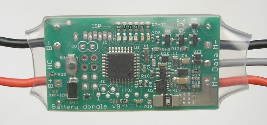
If its too much for you, a guy called Cosas in pedelecforum is selling modules based off my code that does exactly this, basically dongles you put on the Battery connector and can connect any ordinary 36V Battery onto it.


Havent done anything on Bosch so far, i dont have Bosch.


The "how to make a Yamaha battery work" was extremely advanced

Do you care to receive a bms from a Bosch battery type new 400wh, originally with 2900PF cells in it?. Without the cells... to try to make a working unit? :banana:
 
Fun fact: the cheaper 300wh models have LG mG1 cells in that are 2850mAh...

Have to do more testing but when bypassing the bms i get 382wh from a 300wh rated pack....
 
@leffex not really, i dont own a bosch and probably never will consider buying one. but without one, i cant do my research.

the guide is advanced, it requires soldering, electronic and battery safety skills. keep in mind, you cant turn off a battery. soldering the wrong spots could cause your house to burn down.

there are 3 pins on the yamaha bike.
+42V Bat
Signal (5V with high impedance, center pin)
GND (closest to the bike frame)

basically you gotta send a certain data set over a Serial 2400 BAUD connection to the bike every 250milliseconds to keep it alive.
by inverting it and pulling the 5v signal pin to ground at each bit, like with these circuits.
https://i.imgur.com/C3ToiHx.png


in addition (since the yamaha bms is killing itself completely once you desolder it ) you gotta need to add a bms for charging/discharging/overtemp/overcurrent protection. nothing fancy.

this is the latest arduino code.
flash it onto a arduino, put it into your battery. now add the power circuit (dc-dc converter to get 5v out of the 42v battery voltage for the arduino), signal inverter & sender circuit and a voltage-divider for measuring the battery voltage.

this guy made a easy to follow circuit:
https://www.pedelecforum.de/forum/index.php?threads/selbstbau-akku-f%C3%BCr-yamaha-haibike-mit-600wh.41701/page-9#post-1096531

Code:
int b1=255;
int b2=255;
int b3=14;
int b4=6;
int b5;//akku %
int b6=25;
int b7=1;
int b8; //??
int b9; //?? 2-3
int b10; // ?? 22-255
int b11=42;
int b12=248;
int b13=1;
int b14=24;
int b15=17;
int b16; //?? 192-224-240
int b17; // 0-7
int b18; // 0-255
int b19;

int b5t2 = 0;
int index = 0;

b5 = 100;

void setup(){
  Serial.begin(2400,SERIAL_8E1);
}

void loop(){
 
    int b5t = (int)map(analogRead(0),610,707,0,100); //610 = 33v, 707 = 38v

    b5t2 = b5t2 + b5t;
    index = index + 1;
    
    if(index > 20){
      b5 = (int)(b5t2 / 20);
      b5t2 = 0;
      index = 0;
    }
    if(b5 >= 100){ b5 = 100; }
    if(b5 <= 5){ b5 = 5; }

    
  //crc sum
  b19 = ((b1-b2-b3-b4-b5-b6-b7-b8-b9-b10-b11-b12-b13-b14-b15-b16-b17-b18)%256)+256;
 
 
  // 4 mal pro sek.
  delay(250);
 
 
  Serial.write(b1);
  Serial.write(b2);
  Serial.write(b3);
  Serial.write(b4);
  Serial.write(b5);
  Serial.write(b6);
  Serial.write(b7);
  Serial.write(b8);
  Serial.write(b9);
  Serial.write(b10);
  Serial.write(b11);
  Serial.write(b12);
  Serial.write(b13);
  Serial.write(b14);
  Serial.write(b15);
  Serial.write(b16);
  Serial.write(b17);
  Serial.write(b18);
  Serial.write(b19);
 
}
 
so bascially the same behaviour as with the bosch, those also commit suicide as soon as you disconnect a wire.

the only thing you can do for a recell is hooking up secondary wires to a parrallel pack so it never "sees" you swapping the cells.
 
Pwnlord187 said:
If you bypass the discharge on your Yamaha battery pcb (cut the thick red/black wires going to the board from the discharge port, and solder them to the main leads of the pack, which are oval shaped solder pads on each end, the one closest to the port is positive) if you do this you won't be restricted by yamahas discharge limits, which are set to be overly conservative compared to how the cells can actually perform

problem is that if any cell drops below 2.5V it bricks the bms.

i had a brand new open the other day for a paid analysis for several ebike batteries (frock those security torx T10 they have) and the bms is a TI bms chip running in host mode. as soon as it loses power or a major fault occurs it waits for a response from the host (who is at the factory) for action before it re-enables normal operation. its like having a smart bms without a reset button.
 
flippy said:
Pwnlord187 said:
If you bypass the discharge on your Yamaha battery pcb (cut the thick red/black wires going to the board from the discharge port, and solder them to the main leads of the pack, which are oval shaped solder pads on each end, the one closest to the port is positive) if you do this you won't be restricted by yamahas discharge limits, which are set to be overly conservative compared to how the cells can actually perform

problem is that if any cell drops below 2.5V it bricks the bms.

i had a brand new open the other day for a paid analysis for several ebike batteries (frock those security torx T10 they have) and the bms is a TI bms chip running in host mode. as soon as it loses power or a major fault occurs it waits for a response from the host (who is at the factory) for action before it re-enables normal operation. its like having a smart bms without a reset button.

Yea.. while upgrading the haibike I've basically found that it was a domino effect of replacing every single thing that is yamaha on the entire bike. The better route would be to leave it stock, tune it, polish it, charge it, sell it. And instead build an ebike by installing components or a kit to the bike of your choice. In my scenario this isnt an option as Im working on someone else's bike and have gone far beyond the point of no return. So now this bike is a haibike sduro with a Tongsheng tsdz2 750W 52V mid-drive kit. I've installed the bottom bracket by welding together a pipe for the bottom bracket, to 3 other smaller pipes for the frame mount. Ive grinded off some of the sides of the frame near the bottom bracket to allow the tsdz2 to swing back up into the spot the yamaha motor was in. Now im in the process of disassembling 2 36V packs 10S4P (80 cells) and using these cells to create one 52V 14S5P battery pack (70 cells) and wiring them up to a different BMS (the yamaha bms's are in the garbage with the bag tied TIGHT) but removing the cells from these packs has been a struggle, I put blood sweat and tears into it last night LOL Ive gotten to the point of removing the plating from 3S of each pack (with the intent on just pulling these cells out and adding one cell to each bundle, resulting in having 2x 7S5P packs I could series) but even after these cells are exposed with bare ends I still cant f*#%king figure out how to remove them easily. Worse case scenario I might run cables from the individual cells back to each parallel bank (resulting in a pack that drifts out of balance sooner)

Anyone have experience getting these damn cells tfo of these packs?

Thanks
 
flippy said:
Pwnlord187 said:
If you bypass the discharge on your Yamaha battery pcb (cut the thick red/black wires going to the board from the discharge port, and solder them to the main leads of the pack, which are oval shaped solder pads on each end, the one closest to the port is positive) if you do this you won't be restricted by yamahas discharge limits, which are set to be overly conservative compared to how the cells can actually perform
At what voltage does the yamaha and or bosch packs usually cut out at?

Im not sure what the controller cuts out at, or if it even does. If youre concerned about it I'd say just add a second bms and just wire it for discharge protection, or get another charger
 
gamerpaddy

I am trying to replace the bricked BMS on a Yamaha Habike. I can solder and write code for PIC. I can learn Arduino. I don't speak German.
Does your code communicate with the original battery controller chip, and the charger, and the bike? Or would I need a new charger, and a new controller chip?
 
I built a battery dongle / hack for Yamaha and also developed the complete software, see my article here:
https://www.avdweb.nl/solar-bike/batteries/battery-hack
and the Pedelec forum here:
https://www.pedelecforum.de/forum/index.php?threads/yamaha-batterie-hack-mit-fuel-gauge-ltc2944.80440/
***PLEASE Send your messages and questions to the Pedelec forum, then everything stays together***

Yamaha-battery-dongle-PCB-TS.jpg

Characteristics of the Yamaha battery dongle
  • You can use any battery on your Yamaha ebike instead of an expensive original Yamaha battery.
    The battery capacity is measured very accurately with an LTC2944 fuel gauge IC, not just simple voltage measuring.
    Fuel gauge indication with 5 LEDs.
    The dongle turns off automatically when the Yamaha ebike is turned off.
    The battery capacity is stored in an EEPROM so that it is not lost when switched off.
    Data signal short circuit protection
    Very low power consumption
    The dongle can also be used on any other ebike to measure just the battery capacity.
The files are open source on GitHub.
Yamaha-battery-hack-v4-schematic.jpg

Yamaha-battery-hack-v3-PCB.jpg


I have made a new schematic version 4 that still needs to be finished...
 
Great Post! I Implemented this code in a Yahama PasB2 battery for rear carrier. This battery also has an integrated rear light. The rear light is switch via the bicycle handlebar, so the signal will also go via the serial channel. Did anyone figure out how to make the light functional again?

Regards, Robert
 
Hi my yamaha battery just give me.2 flashing lights 1,4. After reading ,I know its dead .
So as the dongle is out of stock ,
Is there anyone that would build me the arduino version please, or point me to someone that sell them. Thanks 👍
 
Back
Top