tonystark20 said:
currently the brake handles I have are modified with a hall effect sensor - they are hooked up to an arduino that controls all the lighting on the trike. (one of the functions I had planned to add was for an emergency stop the brake lights would flash - currently programmed but not turned on as the system has a whole host of other issues)
What kind of issues (for those not already listed in the thread)?
The ASI controller allows for many things including torque ramp up and down for the regen, engine torque % for regen, battery current max during regen as well as a cut off option (no regen) and and separate control pin option for regen. and regen can be controlled with on/off, analog, and via the network (can bus and TTL Rx/Tx) trike is also already equipped with a second throttle that I had intended for using with the brakes I just have to wire the hall effect inside of it.
FWIW, if you're already used to using regular brakes to control the amount of braking you use, it's going to be more natural and more reflexive in a panic stop, etc., to use only the brake lever itself to control the braking.
If you are setting it up to use the brake lever to engage the ebrake, but then use a separate device (throttle, etc) to then control the *amount* of braking, you're increasing your reaction time and complicating the reflex process, potentially enough in the right situation to prevent you from braking sufficiently in time.
If the lever does all the work just like it normally would, then it should allow reaction times and reflexes you already have to work.
")
The way I did mine in the version presently operating is to use a cable-operated throttle that's pulled by the cable-type brake lever, as the analog voltage source. The details are in that linked thread for why it is the way it is, but it basically uses the ebrake switch built into the lever to turn a set of relays on. One of the relays switches out the actual throttle, and switches in the one in the COT, so that as I pull the lever, the COT outputs it's voltage instead of the regular one, and the mechanical stuff is setup so the COT range is the same as the lever range, giving me matched mechanical vs electrical range on the lever.
The way it *will* work when done, because the Lebowski brain has a second analog input that can be used for analog ebraking, is to directly run the COT to the second input so the brain just reads it directly, and no switching/etc is needed, *and* a different response curve can be used fro the brake vs the throttle.
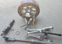
I took the cover off the other side of the motor, it's really hard to tell if it does come out, even if it did there is lots of sealant to remove along with re-running wire.
I fully expect ot have to redo wiring; on mine it's already damaged at the axle exit from the axle breakage. Sealant is relatively easy to deal with, if tedious.
But the why else would the snap ring be there? Plus I can see a spot behind the snap ring that looks to be a keyway.
The strongest hammer I currently own however is a standard ball peen. and it didn't look like anything was budging. might try some penetrating fluid and placing the motor in a way that the stator won't want to move around so much within the magnets. But I have a feeling it may require a press to get out, the machining looks to be of tight tolerance.
Well, in the coming week I'm hoping to get to the QS205 project (along with many others), and if so I'll see if I can get the snap rings off, and use the rubber mallett to try to at least see if the axle will easily move.
First I will have to build a support for the stator itself, securing the stator support core directly surrounding the axle, so that:
--the windings cannot be damaged
--the alloy stator support cannot be damaged
It may be necessary to heat the stator support to cause it to expand, after first freezing the axle to cause it to contract.
but I'll post what I find.