Doc's 24s LIPO charger balancer & quick connect

Hi Doc

Yes my pigtails from hobby city were bad as well, I changed them for some off ebay that were much better, the hobby city ones are using fake JST connectors thats the problem, I have some real JST ones and they are 100% better, I still want rid of them anyway as they are a constant source of problems.

From what i can gather it is better to charge the Lipo cells up to 4.1V whether you are bulk charging or balancing, there is evidence from motor manufacturers that are testing Lipo cells that this can help increase cycle life by quite a bit, couple this with keeping the depth of discharge above 40% which I do anyway should really help the packs last a long time, my packs operating in parallel mean that they never see more than 15A discharge on each pack or 3C this has to help the pack as it is rated up to a max of 25C :twisted: I think they will fall apart first before they stop working :lol: I am hoping for long life with them however it isnt going to break me if they only last a year either 8) I use them every day, just amazing amazing batteries.

Please show us more video of your amazing bike when you get time Doc!!

Knoxie
 
YES! I would like to see more as well! Possibly off road!!
 
with over-night charging is it possible to use a single 3.6v charger to recharge single A123 cells in parallel? would this equate to balancing or does balancing involve (like a graphic equalizer) dynamic lowering of certain battery voltages until all batteries have similar voltages?
Bravo Doc!
 
novembersierra28 said:
with over-night charging is it possible to use a single 3.6v charger to recharge single A123 cells in parallel? would this equate to balancing or does balancing involve (like a graphic equalizer) dynamic lowering of certain battery voltages until all batteries have similar voltages?
Bravo Doc!

with over-night charging is it possible to use a single 3.6v charger to recharge single A123 cells in parallel?

Yes.. no problem.

would this equate to balancing

it's kind of charging so it's also called active balancing because the voltage of each lower cell will go to the higher cell and above until it reach the CC-CV

or does balancing involve (like a graphic equalizer) dynamic lowering of certain battery voltages until all batteries have similar voltages?

This
kind of balancing is called passive balancing just like you explain:lowering of certain battery voltages until all batteries have similar voltages

Parallel cells that are not in charging mode will average their voltage. The higher voltage cell will discharge to the lower and the lower will recharge with the higher until there is no difference of voltage.

When assembling parallel cells THIS IS IMPORTANT TO MAKE SURE THAT THE CELL HAVE THE SAME VOLTAGE OR CLOSE TO TO AVOID TOO HIGH CURRENT THAT TRAVEL FROM TEH LOWER TO THE HIGHER CELLS

Doc
 
Doctorbass said:
novembersierra28 said:
with over-night charging is it possible to use a single 3.6v charger to recharge single A123 cells in parallel?
When assembling parallel cells THIS IS IMPORTANT TO MAKE SURE THAT THE CELL HAVE THE SAME VOLTAGE OR CLOSE TO TO AVOID TOO HIGH CURRENT THAT TRAVEL FROM TEH LOWER TO THE HIGHER CELLS

Doc

Dear Doc

What is the maximum difference without damaging? is it safe to assume that if all the a123's are CHARGED using 3.6v lifepo4 charger and they reach their normal voltage of 3.4v, some of them reach 3.6v as normal voltage, is it right to assume that if i group 3.4v and 3.6v there will be damage?

How much difference can the batteries have without damage in 0.#?volts
 
novembersierra28 said:
Doctorbass said:
novembersierra28 said:
with over-night charging is it possible to use a single 3.6v charger to recharge single A123 cells in parallel?
When assembling parallel cells THIS IS IMPORTANT TO MAKE SURE THAT THE CELL HAVE THE SAME VOLTAGE OR CLOSE TO TO AVOID TOO HIGH CURRENT THAT TRAVEL FROM TEH LOWER TO THE HIGHER CELLS

Doc

Dear Doc

What is the maximum difference without damaging? is it safe to assume that if all the a123's are CHARGED using 3.6v lifepo4 charger and they reach their normal voltage of 3.4v, some of them reach 3.6v as normal voltage, is it right to assume that if i group 3.4v and 3.6v there will be damage?

How much difference can the batteries have without damage in 0.#?volts

It depend on wich range they are!

between 3.5 and 3.6 or 3.7 there is no problem.. 3.5 to 3.7 = no prob

but in the 3.25 to 3.35V range a 100mW difference make bigger difference.

I would say that connecting :

3.30V and 3.40V is ok

3.30V and 3.60V = dont dont that

3.20V and 3.40V = dont do that

3.10V and 3.35V = dont do that

3.20V and 3.30V = ok

2.70V and 3.70V = NEVER ATEMPT TO DO THAT... you will dammage the lower cell

you understand?

Doc
 
Connecting 3.3V to 3.4V is probably not a good idea. At 3.4V the cells can be over 90 percent charged. At 3.3V they might be 50%. That's enough of a difference to cause a lot of current to flow.

Between 3.1V and 3.3V it is very difficult to tell just how much charge is in a LiFePO cell by measuring its voltage. Anything above 3.45V and the cell is pretty much fully charged. See my post at http://endless-sphere.com/forums/viewtopic.php?f=14&t=20698 where I did a lot of testing on A123 cells.
 
texaspyro said:
Connecting 3.3V to 3.4V is probably not a good idea. At 3.4V the cells can be over 90 percent charged. At 3.3V they might be 50%. That's enough of a difference to cause a lot of current to flow.

Between 3.1V and 3.3V it is very difficult to tell just how much charge is in a LiFePO cell by measuring its voltage. Anything above 3.45V and the cell is pretty much fully charged. See my post at http://endless-sphere.com/forums/viewtopic.php?f=14&t=20698 where I did a lot of testing on A123 cells.


Texaspyro,

These numbers i posted are based on true test i did past two years with alot of A123 cells.


Dont forget that for the low cell the voltage rise and that for the high cell the voltage drop... so the delta V between cell is shared between the low and the high cell.

a 100mV diff become around 25mV drop for the high cell and 75mV increase for the low cell...

It depend also on the connection loss you have between cells.

an A123 can take 10A of charging continuous and around 20A burst for few sec

let say 15A charge

so at 100mV a 15A represent 6.6 miliohm... very close to the internal resistance of a single cell.... but when you connect two in parallel that become an equivalent of 13.2 miliohm.. and it's above tghe IR of a single cell.

I still think that a delta 100mV is safe for the overall dynamic voltage range of the cell and the current flow is not in the unsafe area.


Ypedal, thanks for clarifying LIFEPO4 !!

Doc
 
Is the resistance of the wire used to connect the cells in parallel important as well ?

For LiPo, the small 22AWG and JST connectors are pretty restrictive. Wouldn't that "protect" the cell from too much current? Either acting as a "shunt" by restricting the current or as a "fuse" by melting down?
 
I just did a quick test between a 3.305V and 3.413V cell... 18 amps... not good, A123 cells are spec'd at 10 amps. I did not leave them connected to see how long the current would flow at that level.

And yes, balance wires can be fuses.
 
El_Steak said:
Is the resistance of the wire used to connect the cells in parallel important as well ?

For LiPo, the small 22AWG and JST connectors are pretty restrictive. Wouldn't that "protect" the cell from too much current? Either acting as a "shunt" by restricting the current or as a "fuse" by melting down?

It is better to always have lower resistance connections... period.

Wire should not act as shunt or resistance or fuse :shock: since that generate heat and is not controlled and could catch fire.

Doc
 
texaspyro said:
I just did a quick test between a 3.305V and 3.413V cell... 18 amps... not good, A123 cells are spec'd at 10 amps. I did not leave them connected to see how long the current would flow at that level.

And yes, balance wires can be fuses.

Yes... but i did that test too and the voltage quickly adjust so that the current decrease in few seconds.


I guess that 100mV and not 108mV could be like 16A instead of 18A...
dont forget that at these charge current the cell voltage.. even though it<s just few milivolts tha the recharged cell voltage increase fast... and that the discharged cell voltage decrease fast too...

I also did an extreme test..

a 100% charged cells (at 3.700V) and a discharged cell (2.0V) connected in parallel... The current increased to 78A and quickly decreased to around 40A. both tested cell was like new about health before the test

doc
 
Doctorbass said:
I guess that 100mV and not 108mV could be like 16A instead of 18A...

Also, I suspect that I had better connections than you... my cell negatives were connected by less than 1 inch of 10 mil copper soldered to the terminals (DeWalt tabs). The amp meter was connected with two inches of 8 gauge copper...

These tests were done with single A123 cells. Things might be more "interesting" with big boy cells.

Anyway, when paralleling cells, you should first make sure that the cells are as closely matched as possible (voltage, state of charge, capacity, and internal resistance). Your cells will last longer and your pack will work better. Matching cells for capacity and internal resistance is particularly important for best long-term pack performance.
 
texaspyro said:
Matching cells for capacity and internal resistance is particularly important for best long-term pack performance.


you should read my past thread about that since 2007! :wink:

Me and a friend developped a mathlab based software to match perfectly cells with internal resistance and capacity.

You might not know that but i did alot of work on that and built alot of test device about the konion and dewalt cells. from now i discharged and measured capacity and internal resistance of up to 2500 individual cells when building pack for me and folk.

I have all tools for measuring every inportant parameters of cells, and did some research to find correlation between cells capacity and internal resistance vs soc and also age.

Here is few exemple: http://endless-sphere.com/forums/viewtopic.php?f=14&t=2764&hilit=432+cells

file.php


file.php


file.php


Also, I suspect that I had better connections than you... my cell negatives were connected by less than 1 inch of 10 mil copper soldered to the terminals (DeWalt tabs).

If you find better connections than that for A12 cells let me know! :wink:

file.php


Believe me.. I know what i'm talking about when speaking about cell matching! 8)

I agree that every cells should have the closer as possible soc when connected in parallel.

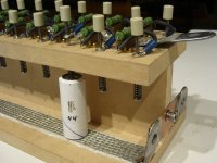
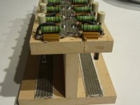
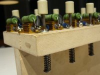
I also built a tool to parallel single cell to equalize them.. 9 not active charging but passive equalization:

I can put any cell that are 65mm long type in paralllel and they can have any individual soc.

This device can be used just to balance or balance charge cells before making a pack.

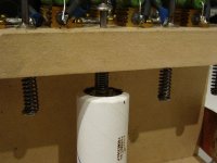
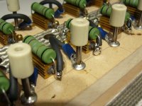
I used large 1" wide copper braid that is a bit soften to take the shape of the cell tab and maximize the contact to the cell in case of light oxidization or debri on thh cell tab and spring loaded negative contact to ensure the contact is firm.

Each cell have one contact that is in serie with a resistor to allow a max current limit of 10A in case where the lowest is 0% soc and the highest is 100% soc

Also when i do a discharge test of a batch of cells, I must ensure every of them is at his 100% soc so the best way is by charging them thru that device. I have a 200A 5V psu so i can charge up to 10A per cells for 20 cells at a time and then i leave them for few hours to ensure they stabilize. but usually i charge them at 1C to get the max capacity IN. I also did capacity test and graph depending on the charge current and discharge current too.


This 20p device is Very usefull!!! for testing and building large pack.


Doc
 

Attachments

  • P1080068_800x600.jpg
    P1080068_800x600.jpg
    72 KB · Views: 1,655
  • P1080069_800x600.jpg
    P1080069_800x600.jpg
    61.8 KB · Views: 1,658
  • P1080070_800x600.jpg
    P1080070_800x600.jpg
    60.7 KB · Views: 1,658
  • P1080072_800x600.jpg
    P1080072_800x600.jpg
    74.6 KB · Views: 1,658
  • P1080073_800x600.jpg
    P1080073_800x600.jpg
    64.7 KB · Views: 1,655
I like it...

How are the connections between the rods and the wires/resistors done? I would not trust any sort of sliding contact. I would want the connection to be like braid soldered to the (pure copper) rod. I would also want the cell contact points on the rods to be gold (or possibly silver) plated. Anything beyond a few hundred milliamps of load then even milliohms of resistance starts to become very significant.

If you really get anal about it, then you start worrying about things like thermoelectric EMFs generated by contact heating and things like what type of solder you used to join what type of metal. Copper oxide to copper junctions have HUGE thermoelectric potentials (over a millivolt/degree). I have built systems when even 0.001C temperature gradients across junctions totally screw things up. I have had to make my own cadmium-tin solder to minimize thermoelectric effects... the stuff has long been out of production/banned.

My CD tab welder can generate over 20,000 amps. The only reason why is utterly ruthless attention to the details. Even 1 milliohm of resistance between the capacitors and the probe tips will kill that level of performance (caps are charged to 20V max).

I did some tests of those black plastic AA battery holders. Utter trash... each cell had at least 0.1 ohms of contact resistance. No wonder they were melting at just 10 amps... Spring loaded contacts just plain suck...
 
texaspyro, This thing is just to passively balance the cells over the time... not an Ri meter!..
who care about a 100% perfect contact or not betwen the cell and their connection to the balancing device...

I only wanted to ensure that the contact are made to ensure every cells are connected together to share current
between the lowest and the highest and avoid having one or more cell not making contact.
in other applications Yes it might be important to have 100% perfect connections.. and maybe supraconductor conduction
if you wish using liquid nitrogen.. but not in the case of my balancing device.

That device is working like a charm and i balanced and assembled over 1200 cells with it from now.

This tool is certainly as useful as my modified CBA II and CC-400 and Ri meter and modified 12s RC charger with Kelvin connections for building pack!

I dreamed about making one for many month and finally decided to build it.

Doc
 
It's a very clean design. Excellent construction.

I am thinking about building a 16 cell CBA type device with a similar construction. I want it to be able to discharge and measure the cells under very precisie conditions... hence my current obsession (no pun intended) with cell contacts. I was thinking of using some old US silver dimes that have been worn slick for the contact buttons. That may not work out too well for making contact to the can of smaller diameter cells.

I have all the cell analysis code written for use on my CD spot welder, but it is a single cell device. It works really well, but takes quite a while to sort through a bucket of cells. Also, unless I disconnect the welder capacitors, I cannot use it to measure cell resistance... something about 3.65 farads of capacitance filtering out the bump in cell voltage spoils the fun...

I could hack up one of my welder boards to build an 18 cell analyzer (it has 18 x IRFP2907 FETs on it) but will probably build a new circuit board. I have not decided whether to use resistive loads (cheap and easy) or active loads (much more complex and versatile)
 
I'd seriously consider using active loads for your CBA-type device as then you don't have to worry about contact or wiring resistance due to the constant-current capabilities of the load. It doesn't care what the resistance (to a point) and will just concentrate on delivering the current you need. As long as the contacts don't heat up enough to affect the cell's performance, you're good to go. :)

And with an active load, it's easy to alternate back and forth between any two current levels and automatically record the cell voltage as it discharges. This lets you plot the internal resistance vs. state-of-charge, temperature, etc.
 
Back
Top