
Alan B
100 GW
Now if it was so easy to analyze and predict the thermal performance. ")


Chuechco said:What is so difficult about a MOSfet master switch?
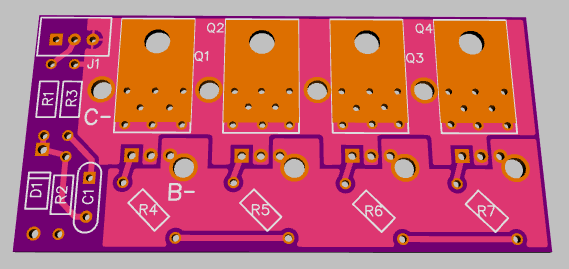
Your design puts the MOSfets horizontal to the board, why not put them vertically up with a proper heatsink attached?
What are the other problems that make such a MOSfet master switch difficult to built?
Chuechco said:What is so difficult about a MOSfet master switch?
Your design puts the MOSfets horizontal to the board, why not put them vertically up with a proper heatsink attached?
What are the other problems that make such a MOSfet master switch difficult to built?
knighty said:if you make them, I'll be interested in buying 4 (2 each for 2 bikes)
is it not possible to mount fets onto the back of the board to double them up that way ?
Alan B said:Welcome to ES.
The FET heat is not actually the problem here, and we're trying to make something compact and easy to produce.
I'd rather not have a hot switch, and the bulk, sharp corners and airflow requirement of a heatsink (heatsinks don't work unless they are hot and have moving air). I've built switches like this before with very little heat rise, if done properly. It really depends on how much average current you are running and how many FETs you parallel.
Teklektic's spreadsheet shows heat rise for bare FETs. We have a lot more heat spreading area than a bare FET, so temperatures should be even lower. The average current on most ebikes is a lot lower than the peak, otherwise the batteries would discharge before the destination was reached. And it would be easy to extend this board to six FETs, or even use two in parallel which is still fairly compact and would carry a lot of current without generating heat.
As an example, on my work-bound commute I use about 13 amp hours in half an hour (and most ebikes use less current than mine). So my average current is about 26 amps. With four 4110's in parallel the current handling is sufficient for 50 amps (with zero heatsink), so this should handle it with lots of margin in terms of FET heating. The PC board traces carrying high current are another problem, but I've taken steps to control that (and standing FETs up makes that worse).
There is one other electronic switch for sale made by an ES member. Was it kfong? I don't think he shared the schematic, and it used up to six FETs standing up with no heatsink, and not a lot of copper for current carrying. It had a micro and latching relay and I don't know how much current it could really handle, though he did mention 10 amps per 4110 FET being no problem. Yes, it was kfong and it is here:
http://endless-sphere.com/forums/viewtopic.php?f=31&t=32135
I could go ahead and lengthen this board for six FETs but I think four is enough for most ebikes and we can always make a longer version when we know what is actually needed. Who needs more than 50 amps average? The vast majority of ebikes will be fine at that level.
Alan B said:I missed this posting earlier, trying to read them from my phone probably.
How many amps at what voltage are you running?
I've paralleled them by stacking them on top of a board, haven't tried on the back, tricky to do that well.
Chuechco said:When looking at teklektik's chart, it all becomes clear to me. There's a constant value which tells you how much temperature above ambient is generated for one watt. R(OJA). The datasheet names it thermal resistance.
So for every watt the MOSfets generates ( P = Id²*Rds(on) ) the MOSfet's junction temperatures rises by 65 degrees.
I wonder by how much you can lower this thermal resistance value (65°C/W) by attaching a heatsink to it? Are values below 30 °C/W achievable? Reducing the thermal resistance by halve would enable the FET to handle 1,41 times more current.
powersupply said:Is 1MOhm enough for the (general?) zener diode to start zenering?