External BLDC Sensor Timing Advance Ideas

Joined
Jun 17, 2011
Messages
13
Location
Indiana
Hello
First off I would just like to say hello! I'm new to the forum (have been reading for a while) and am looking into powered bikes. I do have several questions on E-bikes that I will start another thread for. I am just amazed at how much shear information is on this site. Also, there are some wonderful builds and builders here, great job all!

Anyhow, from reading I did come up with some ideas that may help the guys doing external brushless sensors. It seems (maybe with optical) these systems are providing benefits for their intention; e.g. startup, max rpm, efficiency etc . So, along those lines, I see your next step is to get a timing advance on the sensors if possible. I have a couple thoughts that may work. It's not something I will be jumping on as I haven't decided my setup; however I thought could possibly help someone already there.

Okay, the first version is a hydrodynamic timing advance. This one is a bit easier in concept than carry-out however would be extremely accurate based on RPM.
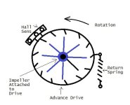
HDTA.jpg

As this is my first time posting,....i hope you see a pic above here, lol.

The photo should help explain the idea here. First you have an impeller mounted to the motor shaft (prolly back on a turnigy) shown in blue. Encasing this and bearing supported on shaft is the Advance drive. You can see it has veins opposing the shown motor rotation. The Hall / Opto sensor would be hard mounted to the Advance drive along with a return spring. Most likely you would want a spring stop for 0 advance. What you end up with, is an extremely loosely coupled drive. The unit should be sealed and filled with a light weight oil, but you could use air also. As the motor spins faster the energy from the impeller is transferred to the Advance drive by the viscous properties of the fluid medium. On the plus side you can very accurately transfer a percentage of energy to the timing advance. A good and bad thing is viscosity; higher means easier design, lower means faster response.

k, nuff of that one.

The second idea I had for controlling the timing advance, is with Titanium Nitinol wire (memory wire). Guess I'll show the pic first here too.
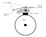
Nitinol Advance.jpg

I used this stuff back when I had a marine store (2000ish), it was fairly new then. The advantage to this system would be a fairly quick and accurate advance; also very durable. In all cases Nitinol wire is affected, ultimately, by temperature; however when used as an actuator this heat is often supplied electrically. For an actuator and Nitinol, when heated the wire will shrink in proportion to the amount of heat it achieves e.g. Watts. The longer the wire, the more it will shrink in length. The higher its' temperature, the shorter it will be (to it's max per length). Once the wire has shorted it will not return to its' original length on it's own. A return spring must be added to stretch the wire back. Here you could run a voltage compared signal (based on motor V or throttle %) that would heat and shorten (advance timing) the wire as power was applied. When I used these I had to parallel 5 wires to get my pull force (5lbs if I remember), but here 1 should do fine.
The good thing is, the wire can shorten very quickly and it doesn't take much power to do so. The down side is there is a slight delay in the spring return. A point of note though, the less force it takes to pull the sensor; the more force the spring can have and thus will return faster.


Sorry for the crummy Paint photo's ;) . Figured an image would explain it all beter.
I hope this may help or give ideas to those pondering timing advance, as well.

I'm sure I'll be posting soon with questions on trying an E-bike. Just wanted to try and offer something first.

Thanks
 
There's a few takes on the timing advance, including an electronic one by Burtie.

(I don't know enough to give any technical reply, though, so you might have to do some searching of the forums for this info)
 
I don't know how Berties doing it, the thought occured to me that the sensors could be physically mounted in the advanced position (whether hall, optical, or "X"), and some type of adjustable electronic device could slow the signal back to neutral at low RPMs.

Someone who knows more about electronics might be able to think of an off-the-shelf gadget and some bits that could be soldered up to automatically advance/retard based on RPM?...
 
A simple but fairly crude adjuster of that sort could be made using a delay line of flip-flops.

Take say 3 flip-flops, connected in-line. That gives you 4 delay options - direct, 1x delay, 2x delay, 3x delay. A simple 555 timer circuit generates a clock, the period of which determines the delay amount. A 4:1 mux lets you select which signal goes to the output. One flip-flop/mux set for each Hall channel, sharing the clock and select signals. That's all very, very simple off-the-shelf logic chips. You'd just need a method to control the select lines, either manually or based on a speed sensor.

You could have more settings by making the chain longer. The delay would be based on time rather than angle, so that would be less-than-ideal. You could probably come up with a method to make it angle-based, but by that point I think you'd be better just doing it with a microcontroller as Burtie is doing.
 
I'm not sure if anyone has done tests on the optimal timing advance for the brushless under various loads and RPM. I know from timing and dyno'ing BDC motors; usually the timing was set @ +1-2 degrees. This of course was more tweaked for a top rpm point, but this could serve as an idea for "how much" max advance may be.

a couple things come to mind. First a 2 degree movement is fairly small both electrically and mechanically. It's possible 2 sensors side by side are, at or more than, the max assumed advance. Also, if any "step" type advance is used; I would expect you wouldn't want those shifts at cruising RPM's, as it could be rough.
** just hit me, mechanical could be solved by just putting each sensor stage on a different point in the motor. E.G - each set 120 degrees (plus advance) apart. That way technically you could have as many halls / steps as you wanted.

I can think of 2 main places to "pick" your signal from, whatever the end design is. First from the output shaft as a rpm /hp (e.g. torque) conversion. Second, most optimally would be to convert off of phase shifting of the motor coils, as that would be the most accurate. Most probably the second option would be carried out / converted from rpm, Volts and amps.

I'm not sure if there is a "easy" answer or that would be built into the controllers (or some controller) already.

*Another thought using torque/ rpm would be to use a CVT variable pulley for advance. I know another mechanical version, but basically as the pulley width shortened (higher rpm); you could easily transfer that diameter change to mechanical linear motion for advancement. Not perfect, but maybe the simplest to execute.

I dunno here it's just thoughts and hopefully help to someone
 
BillMckraken said:
I'm not sure if anyone has done tests on the optimal timing advance for the brushless under various loads and RPM. I know from timing and dyno'ing BDC motors; usually the timing was set @ +1-2 degrees. This of course was more tweaked for a top rpm point, but this could serve as an idea for "how much" max advance may be.

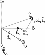
The optimum timing advance depends on the motor inductance and electrical rate of revolution. If you look at the electrical equations, there's an omega*L term that you're trying to cancel out to keep the voltage and current vectors aligned.
 
I apologize if I caused some confusion for referencing 1-2 degree timing. The intention was merely to express that the mechanical spacing of staged hall sensors; might be larger than a viable "active" timing advance would allow. Also, a "possible" idea for timing advance degree, at full rpm and with a steady load.

Since this post was a reference to a variable timing advance I'm assuming many end states of "optimal" advance. It would take a large amount of time and calculation to figure suited advances for all rpms and loadings. If one were to use calculation to determine any given advance point; they would also need to include a few more variables than you mentioned. In addition to the variable Z of the Inductor (as you mentioned) you would need to consider the; magnetic permeability, susceptibility and reluctance, as well as both the static and variable self capacitance of the coil's LC circuit. That's a lot of time and effort done for something easily achieved otherwise, i dunno.

Maybe instead of a degree I could suggest something else. I guess ultimately, with variable timing; you'd want the system to stay slightly advanced during power / loading. Then when a steady load is achieved, you could retard the timing to the "optimal" point of lowest W in. You would want the timing advanced from optimal in all other power / load cases, variable on the load.

Merely throwing out ideas. Hope to help. Sorry again for the confusion.
 
Sorry, I probably didn't make that as clear as I could have either. A picture is worth a thousand words:

SpaceVectors.png

The ideal situation is to have the current vector aligned with the BEMF vector E so that power production is maximized. You can simplify and say that the required timing advance is related to both speed and current. I think that's what you're getting at by saying:
BillMckraken said:
I guess ultimately, with variable timing; you'd want the system to stay slightly advanced during power / loading. Then when a steady load is achieved, you could retard the timing to the "optimal" point of lowest W in. You would want the timing advanced from optimal in all other power / load cases, variable on the load.
Technically you do want the timing to be optimized at all times, but I think what you're implying is advanced from the speed-only timing, which is more or less correct.

I think it would be difficult to control timing based on both parameters using a mechanical system only, but feel free to prove me wrong. A simple setup is probably enough to achieve "good" timing over the full speed range. If you really want to try for "optimum" an electronic system is probably the way to go, based on a lookup table. Really, a timing-based system is just a hack for this anyway because ultimately you're guessing the required advance (or, as you pointed out, making lots and lots of calculations). Field-oriented control is the better solution, which measures the current and BEMF vectors to adjust the timing directly.
 
Ya, it seems we are both describing the same proper scenario; but with different terminology. I think the bulk of this, I can attribute to, me being self-taught. I suppose I also tend to explain things from different perspectives.

To the advance, yes, I'm basically saying advanced from a no-load / speed -only point of view. But mainly for the higher self capacitance caused by the voltage phase leading at that instant in time, early in a cycle.

With the Back EMF control I assume you mean sensorless? Or are you including hall sensor types (since they function of EMF, of which BEMF is larger...usually)?

For the two ideas I showed, sure they are not as perfect as electrical would be.
-The nitinol wire method could be both voltage and current compared to the controller output to motor. The sum of those two variables would determine how much the wire shortened. This should prove fairly accurate mechanically, as the nitinol does respond quickly.

-The fluid method, of course would be more RPM and torque based but that is still power. Depending on the weight of the fluid, you would transfer X amount of energy to the advance drive; at any given static rpm. Current in, from the output shaft perspective, would be realized in the rate of change per unit time / acceleration of the shaft. Larger changes in RPM per unit time would transfer a larger amount of energy to the drive (depending on the viscosity and elasticity of the fluid).

I really was intending to just throw these out here. Again, I don't have an e-bike, but I saw people doing external sensors on these turnigy's. This made me wonder if there would be a "relatively" simple way to advance timing for them. If sensors are outside and free to move, then why not move them to advance.

Just hoping to help
thanks
 
I assume that this thread may have been among the initial reading material? I've been pondering the same thing of late.

I haven't been around the forum long enough to know all the names and be familiar with all the past projects. I did some searching on the username Bertie and didn't come up with anything, perhaps someone has a link to a past thread?


One thing that occurs to me is that the couple of solutions being proposed above seem horrifically complicated. All else being equal, employing a mechanical solution to an electronic problem is rarely the cheapest / most reliable / most efficient option. I often tend to look for inspiration to the automotive community (as they have spend many orders of magnitude more money on R&D over the years than we have) and there's a reason that no new car over last 20 or 30 years has used a mechanical-advance distributor.

My thoughts are more along the lines of spinningmagnets', except I think he has the direction wrong. Ideally, you would want the physical alignment of the sensors to be in the most retarded position, and then use a predictive algorithm to advance the signal at higher RPMs. Why is this? Well, unlike an automotive application, we need to have accurate timing at 0 RPM. If the wheel is stopped, you can't apply a delay to an advanced sensor. So put the sensors at the optimal position for a dead stop, leave the timing neutral at low speeds, and then once wheel RPM is high enough that you can compute a stable cycle time, you can start predictively generating your timing pulses from the previous sensor signal.

In other words, assume that the three sensor/winding combos are referred to as A, B and C. Assuming perfectly neutral timing, the A+B- winding event happens when the A sensor crosses the threshold, the B+C- event when the B sensor crosses, and the C+A- event when the C sensor crosses. (Don't worry about the terms I'm using match your favorite controller. This is an abstract hypothetical.)

Once the wheel is up to speed, you do something counterintuitive. Instead of using the A sensor to determine when to start the A+B- winding event, you use the C sensor. Having already computed the length of time elapsed between sensor events (from which we can compute milliseconds elapsed per degree of wheel rotation), we take the C sensor crossing and use it to start a countdown timer. Thusly, we can generate the A+B- winding event prior to the A sensor crossing happening, by whatever amount we desire.

This is precisely how modern cars with distributorless ignitions work, and it would be relatively trivial to implement.
 
BillMckraken said:
To the advance, yes, I'm basically saying advanced from a no-load / speed -only point of view. But mainly for the higher self capacitance caused by the voltage phase leading at that instant in time, early in a cycle.

To use proper engineering terminology, we say that a motor has a lagging power factor because the current lags behind the voltage (always given as current relative to voltage, not the other way around). The inter-winding capacitance you speak of is present, but relatively small and not significant at the frequencies here - the inductance and resistance are all that matters.

When I refer to field-oriented control, I'm referring to a more advanced control technique. The voltage is controlled by a closed-loop feedback scheme which aims to maximize the so-called "quadrature" component of current (which produces torque) and minimize the "direct" component (which does not). The result is that the voltage vector will be advanced by whatever amount is required regardless of speed, load, etc. This can be done either using Hall sensors or using a sensorless scheme (more difficult).
 
I am well aware of the Engineering use of PF and intentionally did not refer to it as such. I chose to talk about phase, since that's most specifically what "it" is, rather than an industry isolated term. Same with referring to voltage lead instead of a current lag. The voltage is the chicken.....the current is just the egg ;). So ya, I shy away from those references; kinda like the old one "electricity travels from positive to negative.

BillMckraken said:
Second, most optimally would be to convert off of phase shifting of the motor coils, as that would be the most accurate.

rhitee05 said:
The voltage is controlled by a closed-loop feedback scheme which aims to maximize the so-called "quadrature" component of current (which produces torque) and minimize the "direct" component (which does not). The result is that the voltage vector will be advanced by whatever amount is required regardless of speed, load, etc.

Hey! that's what I said already... and much simpler I might add.

sigh
Thanks
 
BillMckraken said:
I am well aware of the Engineering use of PF and intentionally did not refer to it as such. I chose to talk about phase, since that's most specifically what "it" is, rather than an industry isolated term. Same with referring to voltage lead instead of a current lag. The voltage is the chicken.....the current is just the egg ;). So ya, I shy away from those references; kinda like the old one "electricity travels from positive to negative.

You seem to understand what's going on, but you'll have difficulty communicating if you insist on rejecting the standard terminology. But, that's your choice...

BillMckraken said:
Hey! that's what I said already... and much simpler I might add.

The scheme I'm referring to may be roughly the electrical equivalent of the mechanical systems you were describing. However, there is one crucial (and very useful) difference - the FOC method requires no knowledge of the motor characteristics. You could run an RC motor or a hubmotor and the algorithm would perform exactly the same. Pretty much any other method requires you to develop a look-up table with the correct timing advance for a given set of inputs (measure, calculate, whatever).

Just letting you know what's been done, you can do whatever you like.
 
Joe Perez said:
I haven't been around the forum long enough to know all the names and be familiar with all the past projects. I did some searching on the username Bertie and didn't come up with anything, perhaps someone has a link to a past thread?
Answering my own question, I managed to find the thread in question. I haven't completely read through it and digested all of the documentation, but it would appear that Bertie has implemented precisely what I was referring to (albeit externally) and while I haven't found a discussion yet on the theory of operation of the device, the fact that it permits both advance and retard (and incorporates a microprocessor) suggests that he is using timers for predictive advance, which is really the best way to attack this problem.

Links to relevant threads:
http://endless-sphere.com/forums/viewtopic.php?f=2&t=19054
http://endless-sphere.com/forums/viewtopic.php?f=31&t=26068

Very cool stuff.
 
Back
Top