Rolling_Friction
100 mW
- Joined
- Mar 16, 2015
- Messages
- 41
Hi Endless sphere this is my first post.
I have eyed many a post on this forum for both e-bikes, and more recently e-boards over the last months, with the intention of building my own some day. Now I am well on my way to building my first board.
I never long-boarded in my life, and my DIY knowledege is purely self obtained. Not an electrical engineer student (B.A in psychology and minor in philosophy is pretty far removed from that), but all those informative posts I have read had gotten me to think that I could pull off my very own creation.
My intention is to build a functional commuter board that could serve as prototype that I could learn from. Being my first board, I need a base from which I can learn from mistakes and refine my skills. I have access to very basic tools. cordless drill, angle grinder but no drill press or much of anything else for that matter. I see those elegant CNC'd motor mounts and weep
my budget is very limited, so I couldn't justify buying 100$+ motor mounts either. What I do have is a bunch of bicycle parts and other metal scrap.
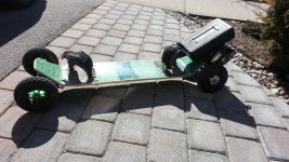
I got my hands on a second-hand mountain board on the cheap. It seemed very basic, no channeled trucks, just some garden variety ones, with a terrible turning radius.
ordered the rest of the parts from hobbyking:
2 Turnigy Aerodrive SK3 - 6364-213kv Outrunners
2 HobbyKing 150A High performance Brushless Car ESC's
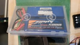
4 ZIPPY Flightmax 5000mAh 3S1P 20C lipos
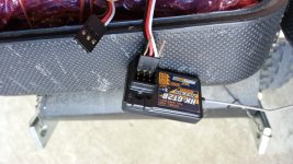
HobbyKing HK-GT2B 3CH 2.4GHz Transmitter and Receiver
a bunch of 4 mm connectors a charger for the lipos, a battery medic and a cell checker.
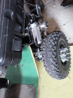
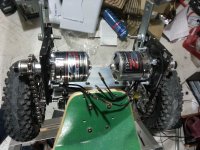
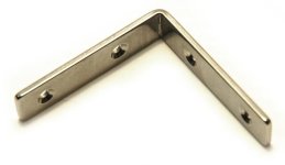
the mount was made from two steel 90 degree angle braces, and a was held in place by a set of "spring coil clamps" which are apparently used to lower/ raise car springs. both parts were purchased at my local Canadian Tire. What holds the actual motors in place on the braces is a pair of dead hard drives, or rather their hollow aluminum shells. I wish I had used a lot more aluminum and a lot less steel, but my local hardware store only sells thin strips of aluminum.
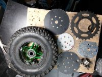
The drive assembly is made of a bicycle chain, which was broken down into 2 smaller chains using a 4$ chain tool from Amazon.ca. the actual sprockets for the wheel are the rear wheel sprocket from 2 bicycle wheels, which I removed from their respective hubs. I went with the biggest sprockets that would fit on my wheels, since the weight of the whole thing is so substantial I figured I could use all the torque I could get.
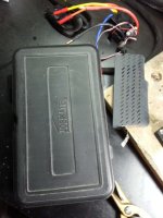
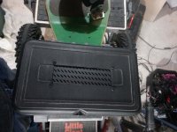
I made a temporary housing for the electrical stuff from an old box for a dremmel-like tool. it was somewhat of a tight fit for all 4 of the lipos. they are arranged in series of 2, so 6s for each motor. I made a square cutout in the box, and fitted a piece of perforated metal on top of it, from a side panel of an old computer case, to let the electronics breath. I think its a tight fit and I will need to find a better housing at some point.
After testing out my board with some success (33 km/h was about as fast as I dared to go), I realized that I didn't like the tension on chain/motor assembly. either it was too tight and I feared wearing it down, or it was too loose and the chain risked coming off the sprocket when I was braking using the motors. So I decided to make a little lever with a small cog (from the rear shifter assembly of the same bicycle that I took the wheel off) to hold the chain down under constant pressure, sort of like how the mountain bikes do it with their chains. the cog is held down constantly by a spring, from the very same shifter. this allowed me to release the tension of the chains slightly. So far it works great, My chains never came off no matter how hard I brake and doesn't add much weight at all. the only down side I immediate noticed is that it makes the board slightly louder. not by much but its something. the added friction is probably not really significant.
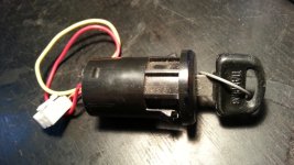
right now its tedious to turn the board on. I need to pop the housing open, fish out two seperate switches in a mess of wires for the ESC's, turn them on, then pop the hood back on.
Can anyone advice how I can splice a switch for the both of them, since the ESC's have 3 wire coming down to the on/off switch, a white red and black. I am assuming I only need to wire the black and red wires, but what does the white do? (its a hobbyKing 150A High performance Brushless Car ESC)
I have eyed many a post on this forum for both e-bikes, and more recently e-boards over the last months, with the intention of building my own some day. Now I am well on my way to building my first board.
I never long-boarded in my life, and my DIY knowledege is purely self obtained. Not an electrical engineer student (B.A in psychology and minor in philosophy is pretty far removed from that), but all those informative posts I have read had gotten me to think that I could pull off my very own creation.
My intention is to build a functional commuter board that could serve as prototype that I could learn from. Being my first board, I need a base from which I can learn from mistakes and refine my skills. I have access to very basic tools. cordless drill, angle grinder but no drill press or much of anything else for that matter. I see those elegant CNC'd motor mounts and weep
my budget is very limited, so I couldn't justify buying 100$+ motor mounts either. What I do have is a bunch of bicycle parts and other metal scrap.
I got my hands on a second-hand mountain board on the cheap. It seemed very basic, no channeled trucks, just some garden variety ones, with a terrible turning radius.
ordered the rest of the parts from hobbyking:
2 Turnigy Aerodrive SK3 - 6364-213kv Outrunners
2 HobbyKing 150A High performance Brushless Car ESC's
4 ZIPPY Flightmax 5000mAh 3S1P 20C lipos
HobbyKing HK-GT2B 3CH 2.4GHz Transmitter and Receiver
a bunch of 4 mm connectors a charger for the lipos, a battery medic and a cell checker.
the mount was made from two steel 90 degree angle braces, and a was held in place by a set of "spring coil clamps" which are apparently used to lower/ raise car springs. both parts were purchased at my local Canadian Tire. What holds the actual motors in place on the braces is a pair of dead hard drives, or rather their hollow aluminum shells. I wish I had used a lot more aluminum and a lot less steel, but my local hardware store only sells thin strips of aluminum.
The drive assembly is made of a bicycle chain, which was broken down into 2 smaller chains using a 4$ chain tool from Amazon.ca. the actual sprockets for the wheel are the rear wheel sprocket from 2 bicycle wheels, which I removed from their respective hubs. I went with the biggest sprockets that would fit on my wheels, since the weight of the whole thing is so substantial I figured I could use all the torque I could get.
I made a temporary housing for the electrical stuff from an old box for a dremmel-like tool. it was somewhat of a tight fit for all 4 of the lipos. they are arranged in series of 2, so 6s for each motor. I made a square cutout in the box, and fitted a piece of perforated metal on top of it, from a side panel of an old computer case, to let the electronics breath. I think its a tight fit and I will need to find a better housing at some point.
After testing out my board with some success (33 km/h was about as fast as I dared to go), I realized that I didn't like the tension on chain/motor assembly. either it was too tight and I feared wearing it down, or it was too loose and the chain risked coming off the sprocket when I was braking using the motors. So I decided to make a little lever with a small cog (from the rear shifter assembly of the same bicycle that I took the wheel off) to hold the chain down under constant pressure, sort of like how the mountain bikes do it with their chains. the cog is held down constantly by a spring, from the very same shifter. this allowed me to release the tension of the chains slightly. So far it works great, My chains never came off no matter how hard I brake and doesn't add much weight at all. the only down side I immediate noticed is that it makes the board slightly louder. not by much but its something. the added friction is probably not really significant.
right now its tedious to turn the board on. I need to pop the housing open, fish out two seperate switches in a mess of wires for the ESC's, turn them on, then pop the hood back on.
Can anyone advice how I can splice a switch for the both of them, since the ESC's have 3 wire coming down to the on/off switch, a white red and black. I am assuming I only need to wire the black and red wires, but what does the white do? (its a hobbyKing 150A High performance Brushless Car ESC)