• Howdy! we're looking for donations to finish custom knowledgebase software for this forum. Please see our Funding drive thread

FLIPSKY new 20s 100A tiny controller (vesc based)

jaykup said:
No idea... they usually don't blow up like that. My guess would be a bad mosfet that shorted out or poor QC/soldering from Flipsky. The mosfets shouldn't switch on until you run the motor wizard.

Are you sure about this? On all the VESCs i have, there's a short tinkling noise from the motor as it starts up. Before touching the throttle. Before any command for power our detection or... Just on boot.

Same for flipsky and my custom ones.
 
Just found the datasheet.
Its a high voltage step down.
Today I will remove the fets, the step down, do some more inspections and measures.
My only suspicious is that the board touch the metal case and shorted.
 
So, hope you succeed with your repair gilbert...

Long story short my esc was not bricked, tho I could certainly be forgiven for thinking so. The red "serial port error" is alarming enough as was repeated detection failure.

I fired up vesc-tool 3.1 and reflashed the bootloader, then the 5.3 stock firmware, and disabled phase filters. The motor wizard spit out some weird detection #s... it ran fine on the stand but was total crap on the street. Ran detection manually and got good #s and was able to actually ride it.

Bottom line, this little box is apparently just a toy, incapable of running a high performance ebike. (Edit: this statement was premature and not entirely accurate).

Continuous throttle cutouts due to some limit or another, zero torque off the line. With field weakening it will eventually spin up but this unit can't handle the heat. (Edit: it wasn't heat, but failure to set absolute max amps high enough out of an abundance of caution...)
 
Does it show temperature errors when you connect to it again? I really think with some thoughtful heat management, there could be surprising performance from such a small package. Maybe wishful thinking for a full sized ebike configuration but there are some people getting decent performance on youtube.

The eskate guys all have chunky heat sinks on their ESCs and can pull some significant power on their rigs, albeit lighter weight obviously.
 
I need wait for the new step down comes to me from China.
Cant find any other with the same pinouts here.
I removed the fet #3 and #4 and my short goes away.
I cant turn on again because the step down was burned too.
I will remove the step down chip, inject external 5v on board and lets see whats happen.
I cant find any other damages but who knows.
The solder quality in this board is a mess.
The fets solder points, near to positive rail is a danger.
Anyway, I will buy a new vesc but a high quality brand this time.
This one will be my test vesc for other projects.
 
MOK- good idea, but debug tab shows no fault codes thrown which is a bit of a surprise...

Just did another test ride. Ran well for two minutes other than the aforementioned poor starting torque then the throttle cutouts kicked in, likely due to heat. Throttle is known good and bike performs perfectly on the test stand with no load.

Setup is 15s pack, 70A battery limit, 100A max motor, 120A absolute max. Battery is 225A capable. IDK what's causing the throttle issue. Controller is in free air but still quickly gets quite warm to the touch. Motor does run smoothly however. Not sure if there are easy tweaks to solve the problems.
 

Attachments

  • 20220330_125005.jpg
    20220330_125005.jpg
    7.4 MB · Views: 1,741
  • 20220330_170028.jpg
    20220330_170028.jpg
    3.7 MB · Views: 1,723
  • 20220330_170119.jpg
    20220330_170119.jpg
    4.2 MB · Views: 1,719
  • 20220330_170244.jpg
    20220330_170244.jpg
    4.2 MB · Views: 1,722
Barncat said:
MOK- good idea, but debug tab shows no fault codes thrown which is a bit of a surprise...

Could do a datalog and see throttle, current, voltage, temperature abnormalities. Should give you a good place to start.
 
Jrbe- if you mean trying to record data thru Android while actually riding, that whole process is over my head. On the test stand the Real Time graphs all look good- problem is that's no load. Only a dyno would suffice...

I can't seem to find any specs online for resistance, inductance, and flux for these common Kunray MY 1020 motors. Or even who actually makes them. Would be valuable to compare to detected #s.

I'm not even maxing out the claimed specs on this 75100, it's the blue board btw. If heat is the culprit after only two minutes that's serious bait and switch, unless I've got a wrong setting somewhere in vesc-tool. There's no way I'd hook my 20s pack to this at present.
 
gilbertojr78 said:
Just found the datasheet.
Its a high voltage step down.

What was the part number? Might be helpful for others who run into the same situation

Barncat said:
throttle cutouts kicked in, likely due to heat.

These units have a few reasons they will cut out. Probably not throttle related.

Soft:
High ESC temp, high motor temp, low voltage. When any of these conditions exist based on the current settings, the unit will slowly reduce the amount of power to prevent these things from going past the set limit. It won't feel like an abrupt cut-out, but rather a gradual reduction of power like an old NiCad power tool running low on batteries.

Hard:
Faults. Over voltage and over absolute current are the most common. Usually these are related to bad settings. These faults will abruptly cut power to the motor for half a second (default, this can be adjusted under motor -> general -> advanced -> fault stop time.) before operating normally again.

Barncat said:
debug tab shows no fault codes

You can type "faults" in the VESC Dev Tools -> VESC terminal section. All faults are cleared when the unit is powered off. So you could go for a longish ride, come back, hook it up to USB while it's still connected to the battery and see if any faults were logged during the ride.

Barncat said:
if you mean trying to record data thru Android while actually riding, that whole process is over my head.

Simplest answer is to buy a metr bluetooth module from shop.metr.at, plug it in to the ESC's COMM port, download the android metr app, and go for a ride. It will show you real-time data like current, watts, voltage, wh/mi, faults, etc. It will also log it so it will look something like this field weakening thermal test ride I did on the hacked firmware.

https://metr.at/r/CFbmc

You can also use the metr bluetooth module with the official VESC android app which supports real-time and logging as well, but without the nice web interface.

The harder but cheaper ($10) way is to buy an NRF51822 or NRF52840 module on ebay/ali, flash firmware from the VESC github onto it, wire it up and use it with the official app. I've done both, but the metr is worth the extra price especially if you can find one used on the forums.
 
jaykup- thanks again for your patience and detailed assistance to those of us less versed in vesc world.

The real key to me getting back on track was your tip about loading the bootloader first, and that in 3.1, the 5.3 firmware actually loads at an indicated 89% done with a red " serial port error" message... Who'da thought... I also noticed Flipsky has updated their web page recently to admonish turning off phase filters along with firmware updates.

While I am quite impatient, I usually persevere. I am loathe to run any component under it's max rated specs, but decided an hour ago to simply drop my battery current setting to 65A, the max motor current to 80A, and absolute max stayed at 120A. Rode around the neighborhood for half an hour with just a couple throttle cutouts. Hard limits not soft. So I think we can safely say a lot of headroom is required between motor and absolute amps. Pretty disappointing on the whole, as mentioned torque off the line is pathetic, but it does spin up to close to 40mph, and could likely do considerably more on my 20s battery should I decide to plug that in. Field weakening is at just 15A, and is more of a hot rod mod than I expected for top end. Don't understand that phenomenon yet, must study.

So at any rate, I've at least isolated the problem- that being advertising hype. I may be able to optimize the heat sinking a bit more...

Has anyone successfully run these for extended periods with absolute max amps jacked up over 120?
 
Barncat said:
jaykup- thanks again for your patience and detailed assistance to those of us less versed in vesc world.

The real key to me getting back on track was your tip about loading the bootloader first, and that in 3.1, the 5.3 firmware actually loads at an indicated 89% done with a red " serial port error" message... Who'da thought... I also noticed Flipsky has updated their web page recently to admonish turning off phase filters along with firmware updates.

While I am quite impatient, I usually persevere. I am loathe to run any component under it's max rated specs, but decided an hour ago to simply drop my battery current setting to 65A, the max motor current to 80A, and absolute max stayed at 120A. Rode around the neighborhood for half an hour with just a couple throttle cutouts. Hard limits not soft. So I think we can safely say a lot of headroom is required between motor and absolute amps. Pretty disappointing on the whole, as mentioned torque off the line is pathetic, but it does spin up to close to 40mph, and could likely do considerably more on my 20s battery should I decide to plug that in. Field weakening is at just 15A, and is more of a hot rod mod than I expected for top end. Don't understand that phenomenon yet, must study.

So at any rate, I've at least isolated the problem- that being advertising hype. I may be able to optimize the heat sinking a bit more...

Has anyone successfully run these for extended periods with absolute max amps jacked up over 120?

It's fine to jack up the abs max a bit higher, that's the current at which it goes "oh shit turn off". It's perfectly sensible to set this to about 1.5x the max motor current. With a 120A max motor current (that's what it's trying to control the current at) I'd probably set 160 to 180A abs max. The FETs should take this fine, it's only about 100 micro seconds they'll experience it for.

Essentially, VESC and FOC works quite differently to the cheap controllers. Grossly simplified, FOC tries to draw an exact sin wave of current with peaks of the motor max current and uses current feedback measurements to correct errors in this. The cheap controllers simulate a voltage wave and just blindly hope it all works out. It's quite realistic to get double the power density with FOC compared to crappy voltage control since FOC doesn't have to cope with huge currents it knows nothing about. The downside is if it has parameters that don't allow it to control the sin wave correctly, it trips out very easily to protect the smaller controller.

I would choose to set this controller at 100A motor max, 150A abs max as a starting point. If you're still getting hard cutouts, it means your settings are wrong or the motor is one of those ones that doesn't like VESC.

Soft cutouts from thermal roll-off show you the point at which you're actually finding the limit of the controller.

Every time you run detection you need to check the parameters. The ones above look plausible for that motor. I don't know if they're right but they're not crazy for an inrunnner that size. If you get factors of 3+different from them, it will not run...
 
mx- thanks for yet another detailed explanation. This is undoubtedly beneficial to many newer users out there in addition to me.

On the heels of burning up that other esc a couple months back I'm a bit a bit more cautious. Sounds like the motor max amps is the # to really respect then , and as you say adjust absolute max amps up proportionally. The hard cutouts I was getting were likely due to the wrong ratio there, not extreme temps. So that would be great, though I can still improve the heat sinking. Will conduct more experiments asap.

I rather like these durable underrated inexpensive motors. As mentioned, it runs super smooth and quiet on FOC, and no more lurchy starts off the line as with the big trap controller or need for the 3 speed switch. So those detected #s above are probably about right but detailed factory specs for comparison would be nice...

Will report back. May be able to get this setup optimized with higher absolute max amps.
 
Set my max battery to 80A, motor max to 100A, and absolute max to 150A. Rode around for half an hour with zero throttle cutouts despite many WOT bursts for 10 seconds, so it was indeed a simple fix. 40mph as indicated by the local permanent radar signs.

Torque is still not great though once past 10mph it's acceptable. And this is with a convex throttle curve, as in boosted early. My 15s p42a pack can deliver way more amps, but not through this controller unfortunately...

Anyone care to to advise me whether to risk playing with the (disabled) MTPA setting? This is an SPM motor not an IPM, though a note came up in vesc-tool during detection that it has saliency that might benefit from using that parameter.

I will likely swap on my 20s battery pack, and lift the field weakening a few more amps (from 15). I suppose I'll try to get near the limit on this little box given the low cost. It's not the $$ it's the nearly month wait for another one if the magic smoke appears.

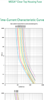
Does anyone have any experience with the (100A) Littelfuse MEGA in the pic? Figured I'd better put something in between battery and 75100...
 

Attachments

  • 20220403_125605.jpg
    20220403_125605.jpg
    3.1 MB · Views: 1,553
Barncat said:
Set my max battery to 80A, motor max to 100A, and absolute max to 150A. Rode around for half an hour with zero throttle cutouts despite many WOT bursts for 10 seconds, so it was indeed a simple fix. 40mph as indicated by the local permanent radar signs.

Torque is still not great though once past 10mph it's acceptable. And this is with a convex throttle curve, as in boosted early. My 15s p42a pack can deliver way more amps, but not through this controller unfortunately...

Anyone care to to advise me whether to risk playing with the (disabled) MTPA setting? This is an SPM motor not an IPM, though a note came up in vesc-tool during detection that it has saliency that might benefit from using that parameter.

I will likely swap on my 20s battery pack, and lift the field weakening a few more amps (from 15). I suppose I'll try to get near the limit on this little box given the low cost. It's not the $$ it's the nearly month wait for another one if the magic smoke appears.

Does anyone have any experience with the (100A) Littelfuse MEGA in the pic? Figured I'd better put something in between battery and 75100...

A 100A fuse won't do much to protect electronic things, it serves to keep the lithium inside your batteries.

Screenshot_20220404-093754.png

As you can see from the screenshot, a100 amp mega fuse actually goes at about 300A in one second, which will easily obliterate your controller.

Even when I set 100A battery currents i use smaller fuses. The 60A fuse will do ~120A for 10s which is enough to get silly speed (20s battery that's like 6-8kW).

Of course, if your WOT for several minutes, you'll blow a 60A fuse.

Make your own decision based on what you're trying to protect.

In standards, fusing is well controlled and there's a lot of derating to be assumed. Typically you would assume it blows at 2x the rated current for safety purposes and would ensure UL certification of the fuse, correct installation, correct voltage rating etc...
 
has anyone tried this with a normal 5V PAS ? how are you suppose to connect it to the controller?

Also, I am wondering, what screen options exist? How do you adjust the power, and turn it on etc? sorry if it sounds a bit noob, but these VESC controllers always confused me... I am still however very interested.

Thanks!
 
John61ct- you can check out my Mongoose Girder in the ebike build section on site. Quick handling steel bmx frame, unnecessarily stiff, but came from factory with a disc brake 20" rear wheel well suited to this application.

mx- thanks for heads up on the fuse and the graph. 99.99% of the time it'll be the controller blowing first, so objective was to protect the battery. I mistakenly assumed a fuse would blow near instantly when subjected to, say, it's labeled rating plus 25% or so...

With this particular fuse the interrupt is not visible but I figured it looks beefy enough to keep from arcing post-break. Not sure whether to trust a conventional 80A automotive bladed fuse in this application. I should downsize this one to 80A or less though if they make that size, will investigate.

Anyway, don't want veer off topic too much but I guess how a 75100 is installed is apropos to the thread. And sorry for leapfrogging your post lqbweb.
 
A fuse that opens at 300Amps for 1sec can give a lot nicer user experience than no fuse depending on the type of failure event.
 
The typical fuse is in place to protect the wiring, not components.
Components / circuits are either "smart" or will likely blow in an event.

@barncat, it's worth considering to move the fuse in the battery box to be first in line in case a short happens.
Also the posts on the fuse look to end up close to your leg with a couple layers of insulation. Worth thinking through what happens if you rub through the tape.

You could look at trying an 80a or maybe even 60a fuse (unless you're going full throttle all the time) if you're attempting to protect components with the fuse.
 
40mph, smooth throttle response from a cheap motor and that tiny form factor seems fairly reasonable for $80-100. Not as impressed with the torque as the other esc but that was like double or triple the cost?

Also forgot to ask earlier, is there any thermal paste between the metal bracket and controller? Or simply bolted to the bracket with the available holes? And do you have an antispark or just plugging in the battery? I really do not want to burn another $55 on an antispark since there have been so many bad reviews of it not handling the current it is supposed to. Really just want to roll the dice on my xt90 antispark set up.

Trying to learn from all your hard work so when the rest of my parts get here I can test out right away. Almost feels like it would have been worth the extra money to get expedited shipping and tracking info from China.
 
is there any thermal paste between the metal bracket and controller?
Yes, there is a thin layer of paste between the metal bar and case.

And do you have an antispark or just plugging in the battery?
Just XT-90 anti spark... the xt90s actually work alright on this controller, the spark you get is small enough to not cause damage. That is not true for pretty much any other controller I own.
 
Hey guys- I learned my lesson a couple months back re not using a fuse. I knew better at the time. Didn't happen fortunately, but (75) p42a cells could make one big-ass fire, and given the propensity of ESCS to fail you don't want a dead shorted battery! I'll be swapping in a 60A MEGA fuse tomorrow which is better suited to this setup per mxlemming's tip. And the wiring in pics above is largely temporary for testing purposes...

MOK- no thermal paste, but over temp shouldn't be a problem if your amp settings are reasonable and in proper ratios. The antispark on my 15s pack works. It doesn't work on my 20s pack, and the 75100 was uncooperative yesterday when I tried setting that up. Despite changing and writing several settings in vesc-tool to 20s, it wouldn't let me exceed 72V max in advanced settings and was unresponsive. Maybe the literal shock of hot plugging, IDK. Whatever...

after 100 miles or so of 15s testing around town, for this PARTICULAR motor I'm probably going back to the generic $100 controller that came with it. Reason- low torque off the line is unsafe in traffic. A higher torque motor might be ok.

It's a bummer because the 75100 is lighter, doesn't require a 3 speed switch, and FOC is smooth and quiet with identical top end to the big trap box.

Anyway, after a month of experimenting, now I know. So carry on gents.

If I make any final observations I'll do in my Mongoose Girder build thread...
 
lqbweb said:
has anyone tried this with a normal 5V PAS ? how are you suppose to connect it to the controller?

i think default controller pins for PAS connections are UART RX & TX (but I have not tested with those pins). 2 wire PAS will work from 5.2. Signal from PAS has to be 3.3V. If the 5V PAS works with 3.3V, signal can be directly used or if PAS supplied with 5V, voltage divider to be used on signal line to make it 3.3V.

lqbweb said:
Also, I am wondering, what screen options exist? How do you adjust the power, and turn it on etc? sorry if it sounds a bit noob, but these VESC controllers always confused me... I am still however very interested.

Run the VESC tool, PAS options are not much & help with each option is helpful. VESC tool can be run from computer/mobile, VESC hardware is not required. Simplest option might be to run in Android. If running on Linux, a few Qt related packages have to be installed (dunno about Windows, as it is out of my door)
 
afzal said:
lqbweb said:
has anyone tried this with a normal 5V PAS ? how are you suppose to connect it to the controller?

i think default controller pins for PAS connections are UART RX & TX (but I have not tested with those pins). 2 wire PAS will work from 5.2. Signal from PAS has to be 3.3V. If the 5V PAS works with 3.3V, signal can be directly used or if PAS supplied with 5V, voltage divider to be used on signal line to make it 3.3V.

lqbweb said:
Also, I am wondering, what screen options exist? How do you adjust the power, and turn it on etc? sorry if it sounds a bit noob, but these VESC controllers always confused me... I am still however very interested.

Run the VESC tool, PAS options are not much & help with each option is helpful. VESC tool can be run from computer/mobile, VESC hardware is not required. Simplest option might be to run in Android. If running on Linux, a few Qt related packages have to be installed (dunno about Windows, as it is out of my door)

But the UART has a 5V line as well right?

Thanks for your support. Do you know where to buy a good PAS that works? I am having some problems finding one actually. It is not clear to me by reading the PR in GitHub if 3 pin PAS will work on 5.3. I guess it is better to just find one quadratic one.
 
Back
Top