Flying Merkel inspired e-bike & sidecar build

Bigwheel said:
The original wheels as you mention were 28" wheels which were the most popular adult size wheel diameter of the era. So my vote would be to use an i45 WTB 700c rim with a 2.5/6 tire to re-create the original look. The wider rim would square off the profile of the tire as it looks like to me in the picture? Set up tubeless you could also run pretty low psi to help enhance the ride quality and traction.

You might comb through Paragon Machine Works website to see what they have on offer that you could use for frame parts?

I didn't see the I45 rims on the WTB website. I wonder if they're discontinued or just out of stock? Wider would be better for the look.

I've been combing thru the product offerings of every North American based frame builder supplier. I'll get there.

What I really want is to find a large lot of frames at a police auction, to see what I can salvage. The left overs I'd build into useable bikes to give to kids in need.
 
I allowed myself to get locked into an idea for being winding legs so that some legs match up with the corresponding set, to solder them together, but realized I could not make it work.

I changed connection types and without thinking I didn't change the bent legs of the coils...

Remedied now... mainly because my service bureau does not yet offer copper as a materials option.

So straight coils it is

AM-JKLUaoIaKVoauM0bB2jpuLBjQtDkfmb_iRKNeh5_RhfKzJGmYlOTATBEReUnQ8j4kkAauS0YlGv9qk-HV5JOenHK457BJjfSrMMxtSEWLg_e5t41UiqA3wJhC6EjKtey9eNdZmVm-_Whkfow_k-L8lW4u=w829-h566-no
 
"I didn't see the I45 rims on the WTB website. I wonder if they're discontinued or just out of stock? "

https://www.wtb.com/products/scraper?variant=1095667752

Apparently out of stock as many parts are these days......An old friend works there and next time I reach out to him I'll see if I can find out whether they are gone for good....there are other options however I think but the key number in rim sizing to me at least is the inner width and many companies use the outer width so that might be a 50mm.
 
Too bad about the no-ship tp Canada, he has several adds on there and it's 40 lbs worth of the stuff per lot.

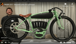
Your build reminds me of a similar build I saw years ago,.. almost forgot, by Maxwell Cycles, really impressive but
board tracks aren't very comfortable. Might be some things here to draw from though.

Youtube video: https://www.youtube.com/watch?v=fhvPB4nn29g

Screenshot 2021-10-27 134031.png
 
APL said:
Your build reminds me of a similar build I saw years ago,.. almost forgot, by Maxwell Cycles, really impressive but
board tracks aren't very comfortable. Might be some things here to draw from though.

I hear you about the comfort... which is specifically why I chose the Merkel, because it doesn't have drop handlebars, it featured a great seat suspension system, and spring frame and forks which lend a little more comfort. I intend to add to the ride comfort with careful tire selection and Cushcore Plus inserts. I am also opting to nix the period pedal placement to move the pedals forward into the core of the motor which I hope will provide better geometry. |

I'll see that as soon as I make a frame jog/strongback that I can position a temporary bottom bracket, seat post, headtube and handlebars how comfortable the bike will be then if necessary adjust it from there. But I do intend to make a Beach cruiser type bike after this one that is strictly built for comfort and slow rolling the Toronto Lakeshore pathways.

Mr Maxwell left out all suspension in his ride, so I'd surely hate it. So would my kidneys.
 
I finished my plans for a die punch to make the copper coil elements. I only needed to make 3 metal parts, because I can use the bottom plate, top plate and pillars from a punch set I have from another project. I decided to simplify the design and use cast polyurethane pads to push the cut copper parts off of the die parts.

78 laser cut coils may be faster, and maybe cheaper. BUT I have almost never built just one of anything so with the die punch I can make hundreds of coil elements before the rubber pads wear enough to need replacing


Not yet complete die punch design... I only need to add the locator pins to the stripper plate, and I'll do that after I purchase copper and see how much overlap of the die I want to have to get the waste to strip off of the punch. The overall footprint is 150 mm x 200 mm x 130 mm high. The die is small enough to use this punch in a 1 ton arbor press.

The base, the punch (dark grey) and the polyurethane pad (in blue which will be cast around the punch die).... the pad gets compressed by the stripper plate when under pressure allowing the copper to be punched out. When the pressure is released the pad pushes the stripper plate back up and it pushes the copper waste off of the punch.

AM-JKLWXx63QJyBibByCI1LXeZfrE2KxAJXYVc-Up9NArVImRpSSQZMKZTCMrxOaU3AN4350-PPAuaLEwdnrw_4jldlVUkqnjVJBC92gIGa06Am1yySI41tz6Wrbfa5SFwvxVHGaoNhTj0TPvegFGaGvGz96=w967-h677-no


The stripper plate

AM-JKLWZ6E2SHVtLhhO-KMYJxQXhjzHIq7nF3cduk_iVLjPElw5f0N4NT8Hue2lVdiLDbhKoCd-kjLgGggbsFNWG8EELTZxhsKEjUPmgo5l8ajWJz2-Zj72SCHkjjdHzBamUXSE2mauzRBxIXTh0FmiQeTIv=w963-h667-no


The die plate, with polyurethane cast "stripper" insert to push the stamped part out of the die plate. The lower stripper plate and pad not shown for clarity.

AM-JKLUPJ6do6Uffn6EzHbAaLU8_rCC0deh822evQv0vsdBIEpwFHbelu3ox6mw0h_Xz_sMTI-Xj-r2dur5Pq86D9PzkNtpdyrlrDQ3KcZ3BBUIfLgOf-9ZJPhkw9Xra44LoOZbwSGnKKtoZfRv9s9aSxopD=w962-h671-no


and finally the top plate, and pillar set. The top plate with the die plate attached is pushed downwards and onto the die punch.

AM-JKLWXiz5Im_xPs-pk-3TZfr7d_SHB5NT7YRx6BkGg6J3nnauEh55Bc2pc0Na_ucGH1Hr_TqMKXDh00pK4uRVb2Jt86xZa3rNPHgenra4q3SF6zPFvj2VjZnoGnRW8gJXjM-YMaDHTe383uK4lSPz6gKWa=w964-h676-no
 
I was stuck a bit on the front fork configuration. I needed to find a source of the appropriate sized tubes to closely match the Merkel spring fork. It has a raked and tapered lower section, welded to a straight wider stationary tube and a sliding tube that nests within the stationary tube along with the springs, washers etc.

The main delay was finding the tapered tube that I could cut out a section with the desired taper, bend a rake into and weld in for the lower section. I wish I could find a round 28 mm tube with a taper, but no such luck

AM-JKLV3FNr0MoPU_sP2jm3dDs_7lZDIPPssTLKvA9LrJdKIVB3MaJ-seic2zTgrjxj1t59yyCr1y1dxLmzHfLWhL3MTBBJFt-DYvbdKgRHb0RQxjkgfPdCAedgSNyqXAnAYbBJHC0uhT15lgS8CPT_wFC5M=w336-h544-no
 
Maybe a modified chainstay would be the way to go?

https://cycle-frames.com/collections/frame-tubes-chain-stays-straight

I apologize for not digging too deep into that site to see if it would actually work, just seemed close to me?
 
I got my 3D printer Tuesday.

I decided to print a fast test print with .28 mm layers, 20% infill and a nice long unsupported overhang, because I was tired of the bent metal pot hooks continually falling off the pot rack due to bend radiuses that were too large...

AM-JKLXBJsofnWBfbjDJpVtHsG1jlh1IeK6abzpiTaONH1bdTSyv0VMhLnGvosNi2FAs0VI5exxsiykRmohIrmXsF0h7ML10NEF1O4vSDXMfOt2TL8HToW4fs8PgGMxHXjUHPcZGzrG8hsS8sObgwidwm5VG=w1010-h757-no


The initial hook was rather larger than necessary and came in at 4 grams. So I decided to make narrower elements and then increase the infill to make more refined hooks which were only 2 grams each. The infill was way too little to support a lot of weight off the end of the hook... basically it was a hollow straw at that point.

AM-JKLWYvPCZKzBDO4GF8qWyFTScUcCoEWBSH0Y_6Mf0lQ02Njefokv03XQ3-CgqmmrR31mYwxPT5u9ozfD2v08Khcsf3LWTABA8gmQ1SojfhbbBn1AVWHMIW3E7pq27KLT9Omd66pk7PX0SuaS03M5PVu0D=w1010-h757-no


I then decided I should try printing multiple parts simultaneously since I will need to be doing that for battery case elements anyway.

AM-JKLUf2SsCpfdOCq12AmOM6UIOcK55U46ojzHstQEN7Tkmh1_veprUR7oRB8YxzrPyN_9U0TwFroRFJCa3QLsLpukp6d6zq4rvQd4lOi67H-lyUYSeQuHW95kmr8KRL4Glf1tNsp7ZvUjg102gUin777R6=w1010-h757-no


Now that the test prints are done and I figured out how to get the BL touch zeroed in, the z height offset configured and cura set up to perform a level mesh each time I print I'm ready to start making headway on my two builds. I'm concentrating on common elements such as the battery pack parts first.

I will be 3D printing dies to stamp the raised dimples on my battery connector plates. Then i'm printing cell spacers and end plates.

Once those parts are done I will be printing an assembly jig to assemble the stator and a jig to lay out and glue my magnet array to the back iron ring.
 
Flying Merkel repos seem to becoming more of a thing?

00v0v_aPkoNW4v1rNz_0CI0t2_600x450.jpg


https://seattle.craigslist.org/tac/bik/d/tacoma-flying-merkel/7420887291.html
 
Nothing much new to add to this thread because I've been relocating shop equipment and finally converting lathe to to a 3ph motor and VFDS.

As soon as that is done I have a couple metal working projects to complete and then I can start my motor prototype.
 
Time for a long awaited update on the Merkel build. So far no progress on the build, BUT much progress on the shop required to complete the build.

The shop relocation is complete. It was extensive process, required new electrical sub-panels etc, new storage, new materials and machinery handling equipment.

Completed the lathe upgrade, gutted the existing electrical cabinet and controls and added completely new control wiring, added rpm read out a 2 HP 3 phase motor and a TECO Westinghouse VFD. Got so much more usable torque I didn''t need a bigger motor.

Acquired 2 new surface grinders, then sold the smaller manual 6x12 and kept the 8x24 hydraulic surface grinder. Had to acquire and install a 7.5 HP rotary phase converter and a 240v to 600v step up transformer to run this machine, but that also means we can add other high voltage equipment in future with ease.

Sold our old milling machine and acquired a Bridgeport Series 1 mill.

To maximize usability of the Mill we decided to replace the lead and cross feed screws and bushings to really tighten up the backlash on those two axes. Then we decided to add a DRO system to the mill as well. That will make drilling holes around a pitch circle very fast and easy. That lead to the decision to add a DRO to the lathe as well. The parts for these most recent projects have started to arrive and we should be good to go for early next week.

That means I should be able to get onto the motor build within a couple of months I hope.
 
Back
Top