Four wire rotor position sensor? In WheelChair motor

JackB

10 W
Joined
Apr 28, 2013
Messages
86
Location
Sacramento, CA
I picked up a free Invacare Arrow electric wheelchair with dead batteries and a missing joystick control.

I am trying to see if I can hack into the motor controller, it uses a MSP430 processor to control the two motors. I could not figure out from the circuit board what the position sensors were so I took apart one of the motors, and it has a position sensor with only 4 wires. The wires go to a circuit board that is nearby some wheel that I can't see very wheel, but its not using the rotor magnets, so not hall sensors.
I am not sure how to power it or what data it produces. I can't turn on the controller as its missing the joystick input unit that is complicated, not a simple input. It has a couple processor that take this input and communicates with the msp430.

I'm thinking it is some kind of optical encoder, the sensor disk is plasticy, and the little circuit board (one the side I can see) has two little 3 pin chips that look like transistors.

Appreciate any help! and btw, I tried searching and it gets errors when trying to view the result threads this morning, seems to work now, but didn't find anything on 4 wire sensors.

I tried using a regular brushless ebike motor controller as they seem to work fine without the hall effect sensors hooked up, and I was very pleasantly surprised to see it runs the motors just fine.
However, I still would like to hack into the existing board as it controls both motors in one board.

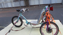
btw, this is for my almost free solar-powered motorhome project..solar panel covered trailer towed by a moped/trike.
Current one uses std bike hub motors, but this trailer has gotten a lot heavier than anticipated, the wheelchair motors are MUCH heavier duty than a bike wheel. Can watch the build on my youtube channel if interested..https://www.youtube.com/watch?v=Lx0oGTplUHo
 

Attachments

  • trikelights.png
    trikelights.png
    1.1 MB · Views: 162
You might look at these threads, it might be a similar motor (don't know without seeing yours, and your post has no pics of them or p/n's, etc from them to look up). Mine uses a SIN/COS sensor with a "plastic" ring magnet around the central shaft; the sensors are linear sensors like those in throttles vs digital ones like in ebike motors.

https://endless-sphere.com/forums/viewtopic.php?f=30&t=32838

https://endless-sphere.com/forums/viewtopic.php?f=30&t=36556

I never really got any further than what's in the thread since I only have one, and I need a pair to use them the way I would like (powered trailer, or a new trike). Have ideas for bike usage, too, but simpler solutions (regular hubmotors) were found for that; these would be "great" for a trike though.
 
Thanks for those links, really appreciate it. I tried to look at them when the system was down.

That motor appears to be similiar to mine, has same shape and connector, but different in a few ways.
Bu I'd assume the sensor is the same. I just don't know which wire is +5v and Gnd, don't want to blow it up giving power to the wrong ones. For now I'm just going to use the existing ebike controllers already in place on the trike.
Remove the wheels and then attach the wheelchair to the back and hookup the controllers to the wheelchair motors.

The big problem with this however, is then I lose the rear disk brakes, and the ebik controllers don't do electrical braking.
Maybe the wheel locks can be pwm to work as brakes? Probably wear them out very quickly. One side seems broken, the manual unlock does not unlock it, I think maybe a spring broke inside or something. The other side works, maybe just one wheel brake be ok for now until I get the oem controller hacked.

I do still have the front wheel brake but not going to stop 700lbs at any speed at all.
 
The sensors, if they're like the ones on mine, are typical linear sensors, so they'll have the same pinout just about all of them do, for whichever casing style yours are in. If you're not sure what that is, you can look them up by the numbers on the face of each sensor.

Then you can follow the +v and ground lines on those sensors to the wires on the board that supply power to it. Note that it may not be 5v, though it is likely to be, there are sensors that run on higher voltages to get higher resolution output and greater signal to noise ratio.

This is a typical sensor:
https://slideplayer.com/slide/12815767/78/images/14/AH+Pins.jpg
AH+Pins[1].jpg
 
JackB said:
Remove the wheels and then attach the wheelchair to the back and hookup the controllers to the wheelchair motors.

The big problem with this however, is then I lose the rear disk brakes, and the ebik controllers don't do electrical braking.
One of my plans for using the motors was to build a hub with spoke flanges and lace that to a bike rim. This hub would bolt over/onto the hub of these motors. I could then use regular bike rim brakes on them.

FWIW, a typical DD hubmotor's spoke flange/magnet rotor happens to be just about the same diameter inside as the outside of the motor's hub, and could be adapted with little effort to make a faceplate that bolts to the outboard side of the rotor (instead of the original bike motor's cover), that then bolts to the face of the powerchair motor's hub. If necessary, a spacer ring bolted on the inboard side of the bike motor's rotor to ensure centering on the pc motor hub. This is what I was going to do to use it on CrazyBike2 at the time I got it, and I did test fittings but never got far enough to actually use the motor. Again this would let me use rim brakes.

I had also planned to figure out how to modify the casings so that I could get a disc caliper to fit over the brake disc that is built into the motor, *or* to bolt a bicycle disc rotor to that disc's hub so it could be accessed / used with a caliper. The whole motor would bolt directly to the trike frame. (I don't have the mounts that come on the powerchairs, but if you do that would make this even easier, and even nicer if they have the suspension some of the mounts do).

Another option is to make a "tophat" adapter that bolts to the face of the pc motor hub and moutns a disc rotor to that, then a bit of framework to mount a caliper to. (I didn't want to go that route because of the extra width it would add to the trike design, but it would work fine if that's not an issue).


Maybe the wheel locks can be pwm to work as brakes? Probably wear them out very quickly.
If yours have solenoids on them. I don't think mine does-I think it only has a manual parking brake, and all other braking was done electronically using the motor itself. But if it yours has a brake solenoid, you could PWM it to engage only lightly all the way to full lockup. If it's like the brushed powerchair motors I've had with solenoid brakes, it probably runs on 24v. I never tried to use them (actualy took them off the motors) so I don't know how well they may work.

Wear...if your rotors are aluminum (pretty sure mine is) it will wear faster than if it were steel, but it might last long enough to work out a better braking system.


One side seems broken, the manual unlock does not unlock it, I think maybe a spring broke inside or something. The other side works, maybe just one wheel brake be ok for now until I get the oem controller hacked.
IIRC the one I have has some plastic parts in there for the manual lock, so if yours is like that it might've broken or worn.


I do still have the front wheel brake but not going to stop 700lbs at any speed at all.
FWIW, the SB Cruiser is that heavy with a load of groceries in there, and the Avid BB7 disc brake with 200mm rotor on it will stop the trike from the 20MPH max it's limited to fairly quickly--the limitation is traction on the front wheel; if I brake too hard it will skid.
 
Got it hooked up for a test. The controller has trouble on start with a load. It shakes a bit before it moves. This is with just one motor powered. Waiting for the cable for the other one. I'm hoping with two motors maybe one will be a better start position.
It has about the same top speed at 24v as the bike wheel.
 

Attachments

  • 20221028_115233[1].jpg
    20221028_115233[1].jpg
    1 MB · Views: 102
Back
Top